


TMP92CM22
2007-02-16
92CM22-26
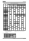
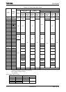
c. STOP mode
When STOP mode is selected, all internal circuits stop, including the internal
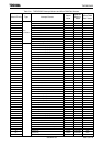
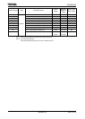
oscillator pin status in STOP mode depends on the settings in the
SYSCR2<SELDRV, DRVE> register.
Table 3.3.5, Table 3.3.6 shows the state of
these pins in STOP mode.
After STOP mode has been released system clock output starts when the
warm-up time has elapsed, in order to allow oscillation to stabilize. Warm-up time
set by SYSCR2<WUPTM1:0> register. See the sample warm-up times in
Table
3.3.4.
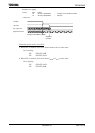
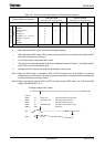
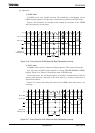
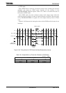
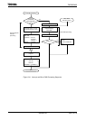
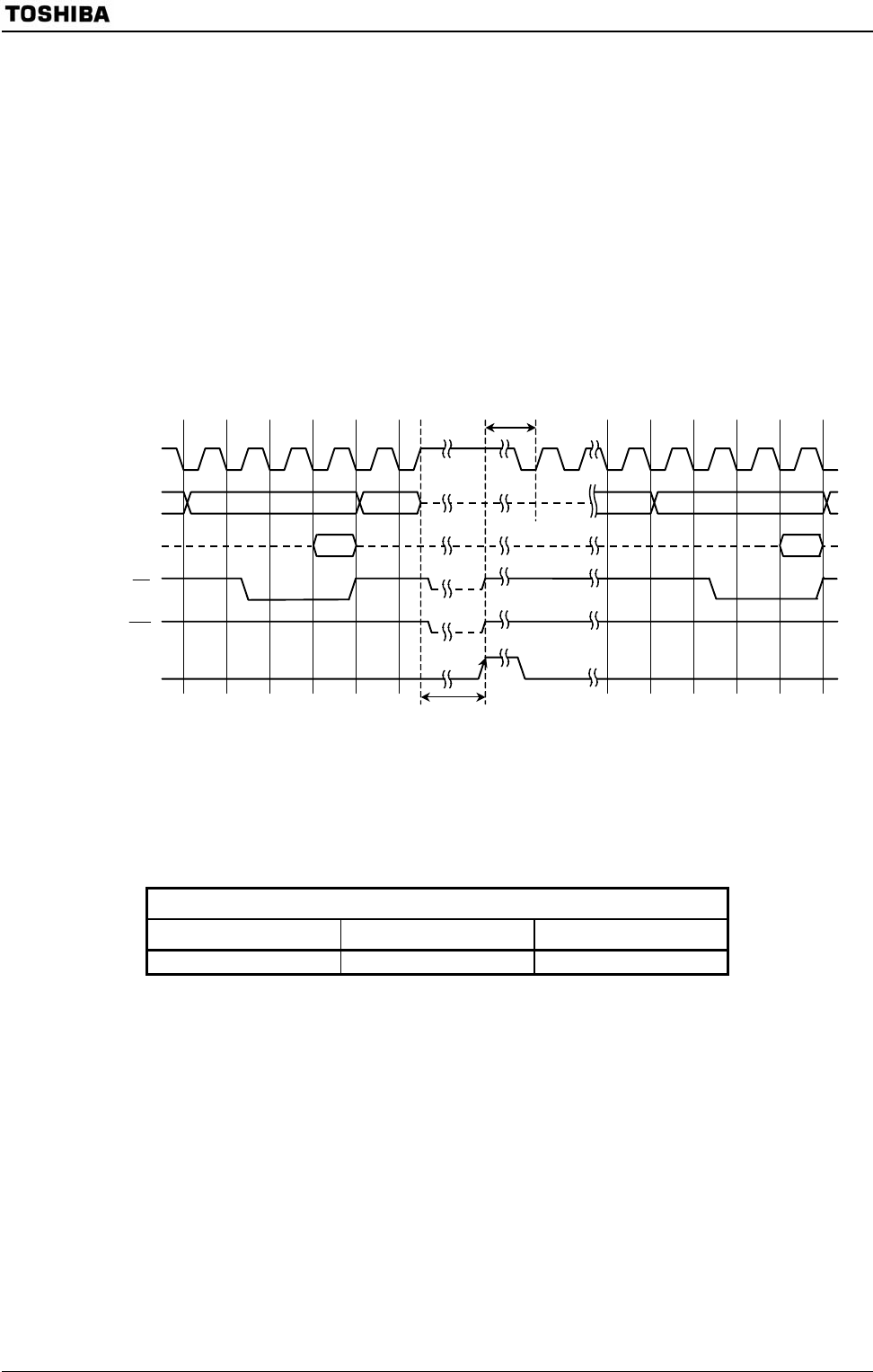
Figure 3.3.8 illustrates the timing for release of the STOP mode halt state by an
interrupt.
Interrupt o
f
releasing halt
Data Data
STOP
mode
X1
A0 to A23
D0 to D15
RD
WR
Warm-up time
Figure 3.3.8 Timing Chart for STOP Mode Halt State Released by Interrupt
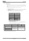
Table 3.3.4 Sample Warm-up Times after Rrelease of STOP Mode
at f
OSCH
= 10 MHz
SYSCR2<WUPTM1:0>
01 (2
8
) 10 (2
14
) 11 (2
16
)
25.6 μs 1.638 ms 6.554 ms