


TMP92CM22
2007-02-16
92CM22-28
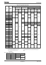
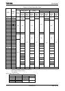
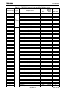
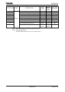
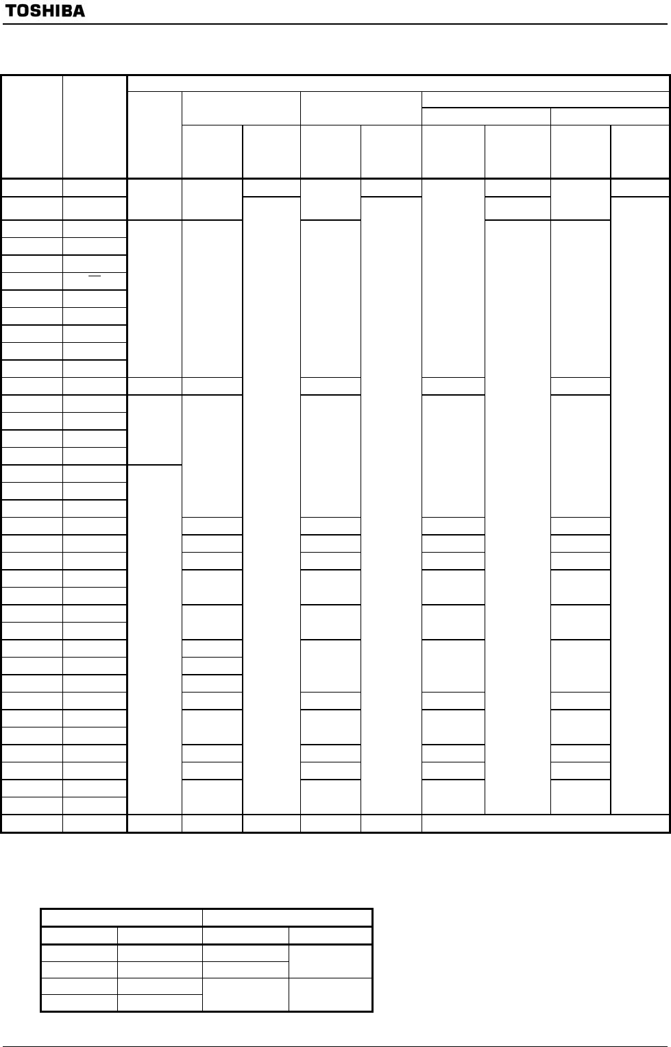
Table 3.3.6 Output Buffer State Table
Note: Condition A/B are as follows.
SYSCR2 register setting HALT mode
<DRVE> <SELDRV> IDLE1 STOP
0 0 Condition B
0 1 Condition A
Condition A
1 0
1 1
Condition B Condition B
Output Buffer State
In HALT mode (IDLE1/STOP)
When the CPU is
Operating
In HALT
mode(IDLE2)
Condition A (Note) Condition B (Note)
Port
Name
Output
Function
Name
During
Reset
When
Used as
Function
Pin
When
Used as
Output
Port
When
Used as
Function
Pin
When
Used as
Output
Port
When
Used as
Function
Pin
When
Used as
Output
Port
When
Used as
Function
Pin
When
Used as
Output
Port
D0-D7 D0-D7 − − − −
P10-P17 D8-D15
OFF
ON upon
external
read
OFF
ON
OFF
P40-P47 A0-A7
P50-P57 A8-A15
P60-P67 A16-A23
P70
RD
P71 WRLL
P72 WRLU
P73 WRUL
P74 WRUU
P75 R/W
ON ON ON
OFF
ON
P76 − OFF − − − −
P80 CS0
P81 CS1
P82 CS2
P83 CS3
ON
P90 SCK
P91 SO
P92 SCL
ON ON OFF ON
PC0 − − − − −
PC1 TA1OUT ON ON OFF ON
PC3 − − − − −
PC5 TA3OUT
PC6 TB0OUT
ON ON OFF ON
PD0 −
PD1 −
− − − −
PD2 TB1OUT0 ON
PD3 TB1OUT1
PF0 TXD0 ON
ON OFF ON
PF1 − − − − −
PF2 SCLK0
PF3 TXD1
ON ON OFF ON
PF4 − − − − −
PF5 SCLK1 ON ON OFF ON
PF6 −
PF7 −
OFF
−
ON
−
ON
−
OFF
−
ON
X2 − − ON − IDLE1: ON, STOP: High level output
ON: The buffer is always turned on. When the bus is released,
however ,output buffers for some pins are turned off.
OFF: The buffer is always turned off.
−: No applicable