


II CORE BLOCK: BCU (Bus Control Unit)
S1C33210 FUNCTION PART EPSON B-II-4-25
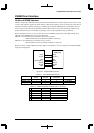
Column address size
When accessing DRAM, addresses are divided into a row address and a column address as they are output.
Choose the size of this column address using RCA, as shown below.
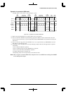
Table 4.16 Column Address Size
RCA1 RCA0 Column address size
11 11
10 10
01 9
00 8
The initial default size is 8 bits. Choose the desired size according to the address input pins of the DRAM to be
used.
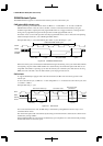
The row addresses output synchronously with falling edges of the #RAS signal are derived from the CPU's
internal 28-bit addresses by logically shifting them to the right by an amount equal to the column address size.
The MSB contains a 1. The column addresses are output to the address bus along with the falling edges of the
#CAS signal. These addresses are derived directly from the CPU's internal 28-bit addresses.
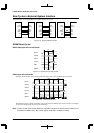
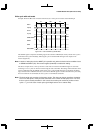
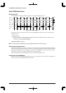
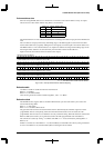
Figure 4.28 shows the contents of the row addresses thus output.
28-bit CPU internal address
T = "1", 0–27: Bit number of CPU internal address
27 26 25 24 23 22 21 20 19 18 17 16 15 14 13 12 11 10 9 8 7 6 5 4 3 2 1 0
(1) Row address when column address is set to 8 bits
27 26 25 24 23 22 21 20 19 18 17 16 15 14 13 12 11 10 9 8T T T T T T T T
(2) Row address when column address is set to 9 bits
27 26 25 24 23 22 21 20 19 18 17 16 15 14 13 12 11 10 9T T T T T T T T
(3) Row address when column address is set to 10 bits
27 26 25 24 23 22 21 20 19 18 17 16 15 14 13 12 11 10T T T T T T T T
(4) Row address when column address is set to 11 bits
27 26 25 24 23 22 21 20 19 18 17 16 15 14 13 12 11T T T T T T T T
T
T
T
T
T T
Figure 4.28 Example of Row/Column Address Mapping
Refresh enable
Use RPC2 to enable or disable the internal refresh function.
RPC2 = "1": Enabled
RPC2 = "0": Disabled (default)
After choosing the desired refresh method using RPC1, write "1" to RPC2.
Refresh method
The DRAM interface supports both a CAS-before-RAS refresh cycle and a self-refresh cycle. Choose the
desired method using RPC1.
RPC1 = "1": Self-refresh
RPC1 = "0": CAS-before-RAS refresh
The generation interval of the CAS-before-RAS refresh is determined by the underflow signal of an 8-bit
programmable timer 0. Consequently, before the CAS-before-RAS refresh can be executed, the 8-bit
programmable timer 0 must be set to obtain the necessary underflow timing. When this method is selected and
RPC2 is enabled, the refresh cycle is generated each time the 8-bit programmable timer 0 underflows.
The self-refresh is started by writing "1" to RPC2 while RPC1 = "1" and is terminated by clearing RPC1 or
RPC2 to "0".
If RPC1 is switched over when RPC2 = "1" (refresh enabled), an undesirable self-refresh cycle is generated. So
be sure to clear RPC2 to "0" (refresh disabled) before selecting the refresh method.