III PERIPHERAL BLOCK: INPUT/OUTPUT PORTS
B-III-9-20 EPSON S1C33210 FUNCTION PART
SPPT7–SPPT0: Input polarity selection (D[7:0]) / Port interrupt input polarity select register (0x402C8)
Selects input signal porarity for port interrupt generation.
Write "1": High level or Rising edge
Write "0": Low level or Falling edge
Read: Valid
SPPTx is the input polarity select bit corresponding to the FPTx interrupt. When SPPTx is set to "1", the FPTx
interrupt will be generated by a high level input or at the rising edge. When SPPTx is set to "0", the interrupt will be
generated by a low level input or at the falling edge. An edge or a level interrupt is selected by the SEPTx bit.
At cold start, SPPT is set to "0" (low level). At hot start, SPPT retains its state from prior to the initial reset.
SEPT7–SEPT0: Edge/level selection (D[7:0]) / Port interrupt edge/level select register (0x402C9)
Selects an edge trigger or a level trigger for port interrupt generation.
Write "1": Edge
Write "0": Level
Read: Valid
SEPTx is the edge/level select bit corresponding to the FPTx interrupt. When SEPTx is set to "1", the FPTx interrupt
will be generated at the signal edge. Either falling edge or rising edge can be selected by the SPPTx bit. When SEPTx
is set to "0", the interrupt will be generated by the level (high or low) specified with the SPPTx bit.
At cold start, SEPT is set to "0" (level). At hot start, SEPT retains its state from prior to the initial reset.
SPPK11–SPPK10:
FPK1 interrupt input port selection (D[3:2]) / Key input interrupt select register (0x402CA)
SPPK01–SPPK00: FPK0 interrupt input port selection (D[1:0]) / Key input interrupt select register (0x402CA)
Select an input-pin group for key interrupt generation.
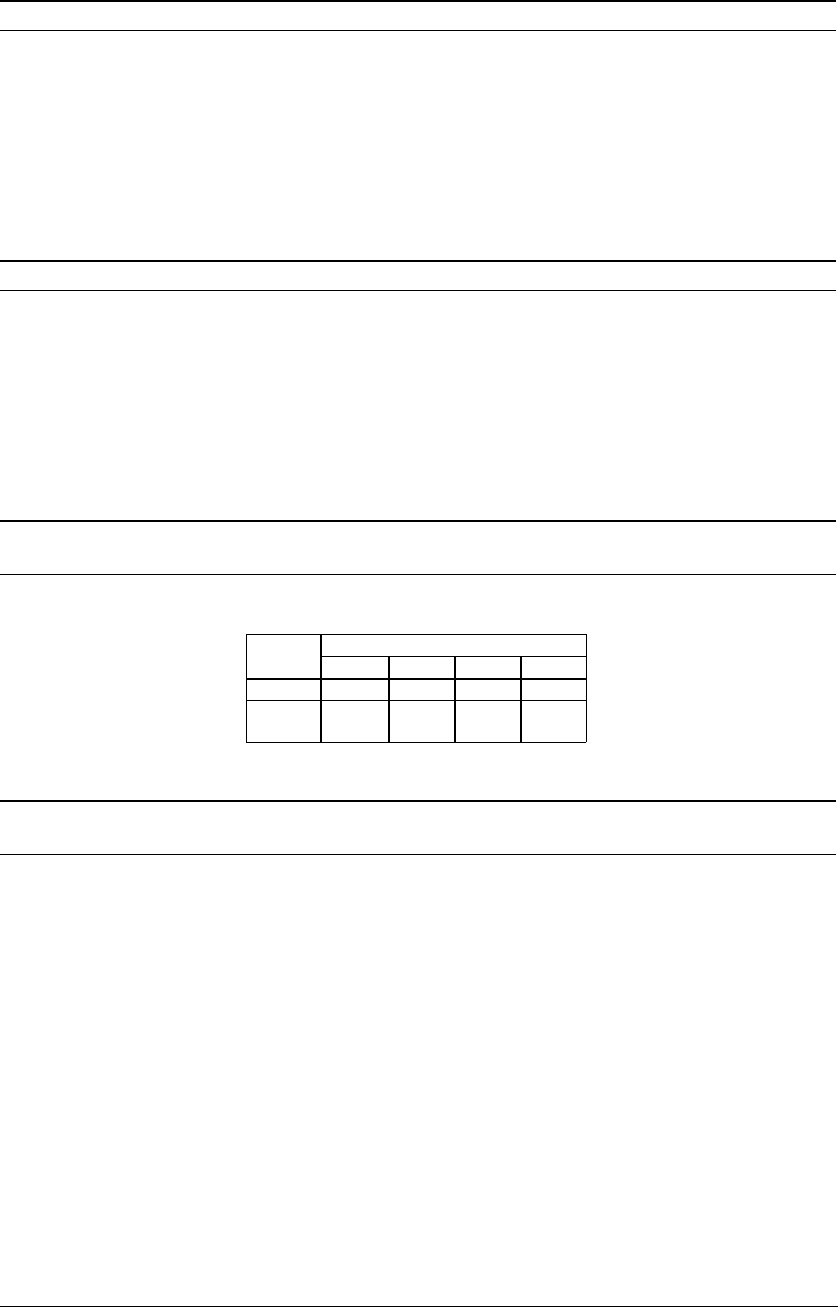
Table 9.12 Selecting Pins for Key Input Interrupts
Interrupt SPPK settings
system 11 10 01 00
FPK1 P2[7:4] P0[5:4] CP[3:0] K6[3:0]
FPK0 P2[4:0] P0[4:0] K6[3:0]
CP0
K5[2:0]
CP4
At cold start, SPPK is set to "00". At hot start, SPPK retains its state from prior to the initial reset.
SCPK13–SCPK10: FPK1 input comparison (D[3:0]) / FPK1 input comparison register (0x402CD)
SCPK04–SCPK00: FPK0 input comparison (D[4:0]) / FPK0 input comparison register (0x402CC)
Sets the conditions for key-input interrupt generation (timing of interrupt generation).
Write "1": Generated at falling edge
Write "0": Generated at rising edge
Read: Valid
SCPK0[4:0] is compared with the input state of five bits of the FPK0 input ports, and SCPK1[3:0] is compared with
the input state of four bits of the FPK1 input ports, and when a change in states from a matched to an unmatched state
occurs in either, an interrupt is generated (except for the inputs disabled from interrupt by the SMPK register).
At cold start, SCPK is set to "0" (rising edge). At hot start, SCPK retains its state from prior to the initial reset.


