


III PERIPHERAL BLOCK: 16-BIT PROGRAMMABLE TIMERS
B-III-4-2 EPSON S1C33210 FUNCTION PART
I/O Pins of 16-Bit Programmable Timers
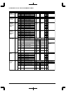
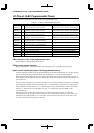
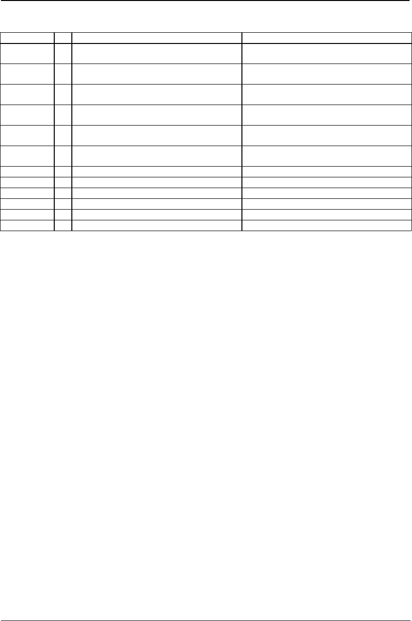
Table 4.1 shows the input/output pins used for the 16-bit programmable timers.
Table 4.1 I/O Pins of 16-Bit Programmable Timer
Pin name I/O Function Function select bit
P10/EXCL0/
T8UF0/DST0
I/O I/O port / 16-bit timer 0 event counter input (I) /
8-bit timer 0 output (O) / DST0 output (Ex)
CFP10(D0)/P1 function select register(0x402D4)
CFEX1(D1)/Port function extension register(0x402DF)
P11/EXCL1/
T8UF1/DST1
I/O I/O port / 16-bit timer 1 event counter input (I) /
8-bit timer 1 output (O) / DST1 output (Ex)
CFP11(D1)/P1 function select register(0x402D4)
CFEX1(D1)/Port function extension register(0x402DF)
P12/EXCL2/
T8UF2/DST2
I/O I/O port / 16-bit timer 2 event counter input (I) /
8-bit timer 2 output (O) / DST2 output (Ex)
CFP12(D2)/P1 function select register(0x402D4)
CFEX0(D0)/Port function extension register(0x402DF)
P13/EXCL3/
T8UF3/DPCO
I/O I/O port / 16-bit timer 3 event counter input (I) /
8-bit timer 3 output (O) / DPCO output (Ex)
CFP13(D3)/P1 function select register(0x402D4)
CFEX1(D1)/Port function extension register(0x402DF)
P15/EXCL4
/#DMAEND0
I/O I/O port / 16-bit timer 4 event counter input (I) /
High-speed DMA Ch.0 end signal output (O)
CFP15(D5)/P1 function select register(0x402D4)
P16/EXCL5
/#DMAEND1
I/O I/O port / 16-bit timer 5 event counter input (I) /
High-speed DMA Ch.1 end signal output (O)
CFP16(D6)/P1 function select register(0x402D4)
P22/TM0 I/O I/O port / 16-bit timer 0 output CFP22(D2)/P2 function select register(0x402D8)
P23/TM1 I/O I/O port / 16-bit timer 1 output CFP23(D3)/P2 function select register(0x402D8)
P24/TM2 I/O I/O port / 16-bit timer 2 output CFP24(D4)/P2 function select register(0x402D8)
P25/TM3 I/O I/O port / 16-bit timer 3 output CFP25(D5)/P2 function select register(0x402D8)
P26/TM4 I/O I/O port / 16-bit timer 4 output CFP26(D6)/P2 function select register(0x402D8)
P27/TM5 I/O I/O port / 16-bit timer 5 output CFP27(D7)/P2 function select register(0x402D8)
(I): Input mode, (O): Output mode, (Ex): Extended function
TMx (output pin of the 16-bit programmable timer)
This pin outputs a clock generated by the timer x.
EXCLx (event counter input pin)
When using the timer x as an event counter, input count pulses from an external source to this pin.
How to set the input/output pins of 16-bit programmable timers
All clock output pins used by the 16-bit programmable timers are shared with I/O ports. At cold start, all these
pins are set for the I/O port pins P2x (function select bit CFP2x = "0"), and go into high-impedance.
When using the clock output function of the 16-bit programmable timer, select the desired timer and write "1"
to the function select bit CFP2x for the corresponding pin. At hot start, these pins retain their status before from
prior to the reset.
All event-counter input pins are also shared with I/O-ports. At cold start, the EXCL[3:0] pins are set for debug
signal output pins (function extension bit CFEX[1:0] = "1") and the EXCL[5:4] pins are set for I/O-port pins
P1[5:4] (function select bit CFP1[5:4] = "0"). When using the event counter function, select the desired timer
and write "1" to the function select bit CFP1x and write "0" to the function select bit CFEXx for the
corresponding pin.
Note that these pins are also shared with output pins for the 8-bit programmer timers, etc. When the
input/output pins are set in input mode, they function as event counter inputs. Therefore, it is necessary to set
the I/O port's I/O control bit IOC1x to "0" in advance. At cold start, these pins are set in input mode. At hot
start, they retain their status from prior to the reset.