


IV ANALOG BLOCK: A/D CONVERTER
S1C33210 FUNCTION PART EPSON B-IV-2-5
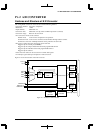
Control and Operation of A/D Conversion
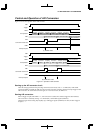
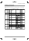
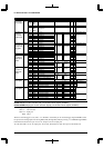
Figure 2.2 shows the operation of the A/D converter.
ADE
Trigger
ADST
A/D operation
ADD
ADF
Conversion-result read
OWE
Interrupt request
AD0 AD0
Sampling Conversion
AD1 AD1
Sampling Conversion
AD2
AD0 converted data AD1 converted data
(When AD0 to AD2 are converted)
AD2 converted data
ADD is overwritten
AD2
Sampling Conversion
(1) Normal mode
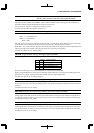
ADE
Trigger
ADST
A/D operation
ADD
ADF
Conversion-result read
OWE
Interrupt request
AD0-1 AD0-1
Sampling Conversion
AD0-2 AD0-2
Sampling Conversion
AD0-3
AD0-1 converted data AD0-2 converted data
(When only AD0 is converted)
Reset in software
invalid
Sampling Conversion
(2) Continuous mode
Figure 2.2 Operation of A/D Converter
Starting up the A/D converter circuit
After the settings specified in the preceding section have been made, write "1" to ADE (D2) / A/D enable
register (0x40244) to enable the A/D converter. The A/D converter is thereby readied to accept a trigger to start
A/D conversion. To set the A/D converter again, or if it is not be used, set ADE to "0".
Starting A/D conversion
When a trigger is input while ADE = "1", A/D conversion is started. If a software trigger has been selected,
A/D conversion is started by writing "1" to ADST (D1) / A/D enable register (0x40244).
Only the trigger selected using TS[1:0] (D[4:3]) / A/D trigger register (0x40242) are valid; no other trigger is
accepted.