


II CORE BLOCK: ITC (Interrupt Controller)
B-II-5-18 EPSON S1C33210 FUNCTION PART
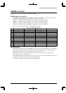
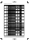
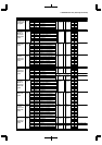
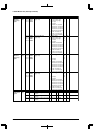
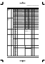
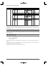
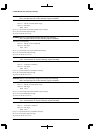
NameAddressRegister name Bit Function Setting Init. R/W Remarks
–
A10BW1
A10BW0
A10DRA
A9DRA
A10SZ
A10DF1
A10DF0
–
A10WT2
A10WT1
A10WT0
DF-B
DA
D9
D8
D7
D6
D5
D4
D3
D2
D1
D0
reserved
Areas 10–9
burst ROM
burst read cycle wait control
Area 10 burst ROM selection
Area 9 burst ROM selection
Areas 10–9 device size selection
Areas 10–9
output disable delay time
reserved
Areas 10–9 wait control
––
–
1 Used 0 Not used
1 Used 0 Not used
1 8 bits 0 16 bits
–
0
0
0
0
0
1
1
–
1
1
1
–
R/W
R/W
R/W
R/W
R/W
–
R/W
0 when being read.
0 when being read.
0048126
(HW)
1
1
0
0
1
0
1
0
A10BW[1:0] Wait cycles
3
2
1
0
1
1
0
0
1
0
1
0
A10DF[1:0] Number of cycles
3.5
2.5
1.5
0.5
1
1
1
1
0
0
0
0
1
1
0
0
1
1
0
0
1
0
1
0
1
0
1
0
A10WT[2:0] Wait cycles
7
6
5
4
3
2
1
0
Areas 10–9
set-up register
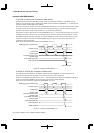
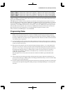
The following collectively explains the basic functions of each control register/bit. For details about individual
interrupt systems and the contents classified by an interrupt factor, refer to the descriptions of the peripheral circuits
in this manual.
Pxxx2–Pxxx0: Interrupt priority register
Set the priority levels of each interrupt system in the range of 0 to 7.
If this register is set below the IL value of the PSR, no interrupt is generated. The value of this register when initially
reset is indeterminate.
Exxx: Interrupt enable register
Enable or disable interrupt generation to the CPU.
Write "1": Interrupt enabled
Write "0": Interrupt disabled
Read: Valid
Interrupts are enabled when the corresponding bits of this register are set to "1" and are disabled when the bits are
set to "0".
For the interrupt factors used to request IDMA invocation or clear the standby mode, the corresponding interrupt
enable register bit must be set for interrupt enable.
When initially reset, this register is set to "0" (interrupt disabled).