


III PERIPHERAL BLOCK: 16-BIT PROGRAMMABLE TIMERS
B-III-4-6 EPSON S1C33210 FUNCTION PART
Resetting the counter
Each timer includes the PRESETx bit to reset the counter.
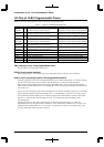
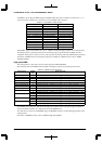
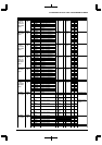
Timer 0 reset: PRESET0 (D1) / 16-bit timer 0 control register (0x48186)
Timer 1 reset: PRESET1 (D1) / 16-bit timer 1 control register (0x4818E)
Timer 2 reset: PRESET2 (D1) / 16-bit timer 2 control register (0x48196)
Timer 3 reset: PRESET3 (D1) / 16-bit timer 3 control register (0x4819E)
Timer 4 reset: PRESET4 (D1) / 16-bit timer 4 control register (0x481A6)
Timer 5 reset: PRESET5 (D1) / 16-bit timer 5 control register (0x481AE)
Normally, reset the counter before starting count-up by writing "1" to this control bit.
After the counter starts counting, it will be reset by comparison match B.
Timer RUN/STOP control
Each timer includes the PRUNx bit to control RUN/STOP.
Timer 0 RUN/STOP control: PRUN0 (D0) / 16-bit timer 0 control register (0x48186)
Timer 1 RUN/STOP control: PRUN1 (D0) / 16-bit timer 1 control register (0x4818E)
Timer 2 RUN/STOP control: PRUN2 (D0) / 16-bit timer 2 control register (0x48196)
Timer 3 RUN/STOP control: PRUN3 (D0) / 16-bit timer 3 control register (0x4819E)
Timer 4 RUN/STOP control: PRUN4 (D0) / 16-bit timer 4 control register (0x481A6)
Timer 5 RUN/STOP control: PRUN5 (D0) / 16-bit timer 5 control register (0x481AE)
The timer starts counting when "1" is written to PRUNx. The clock input is disabled and the timer stops
counting when "0" is written to PRUNx.
This RUN/STOP control does not affect the counter data. Even when the timer has stopped counting, the
counter retains its count so that the timer can start counting again from that point.
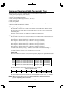
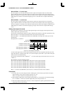
If the count of the counter matches the set value of the comparison data register during count-up, the timer
generates a comparison match interrupt.
When the counter matches comparison data B, an interrupt is generated and the counter is reset. At the same
time, the values set in the compare register buffer are loaded to the compare data register if SELCRBx is set to
"1".
The counter continues counting up regardless of which interrupt has occurred. In the case of a comparison B
interrupt, the counter starts counting beginning with 0.
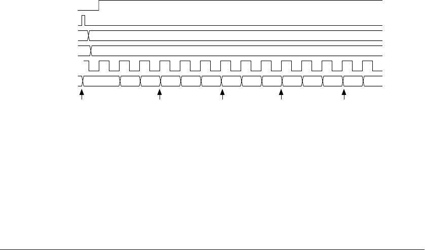
When both the timer RUN/STOP control bit (PRUNx) and the timer reset bit (PRESETx) are set to "1" at the
same time, the timer starts counting after resetting the counter.
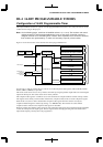
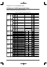
PRUNx
PRESETx
CRxA
CRxB
Input clock
TCx
Reset Comparison A
interrupt
Reset and
Comparison B
interrupt
Comparison A
interrupt
Reset and
Comparison B
interrupt
0x2
012 3 4 5 0 1 2 3 4 5 0 1
0x5
Figure 4.2 Basic Operation Timing of Counter
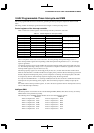
Reading counter data
The counter data can be read out from the following addresses shown below at any time:
Timer 0 counter data: TC0[15:0] (D[F:0]) / 16-bit timer 0 counter data register (0x48184)
Timer 1 counter data: TC1[15:0] (D[F:0]) / 16-bit timer 1 counter data register (0x4818C)
Timer 2 counter data: TC2[15:0] (D[F:0]) / 16-bit timer 2 counter data register (0x48194)
Timer 3 counter data: TC3[15:0] (D[F:0]) / 16-bit timer 3 counter data register (0x4819C)
Timer 4 counter data: TC4[15:0] (D[F:0]) / 16-bit timer 4 counter data register (0x481A4)
Timer 5 counter data: TC5[15:0] (D[F:0]) / 16-bit timer 5 counter data register (0x481AC)