


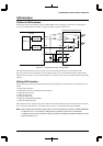
III PERIPHERAL BLOCK: SERIAL INTERFACE
S1C33210 FUNCTION PART EPSON B-III-8-17
The transfer status can be checked using the transmit-completion flag (TENDx).
Ch.0 transmit-completion flag: TEND0 (D5) / Serial I/F Ch.0 status register (0x401E2)
Ch.1 transmit-completion flag: TEND1 (D5) / Serial I/F Ch.1 status register (0x401E7)
Ch.2 transmit-completion flag: TEND2 (D5) / Serial I/F Ch.2 status register (0x401F2)
Ch.3 transmit-completion flag: TEND3 (D5) / Serial I/F Ch.3 status register (0x401F7)
This bit goes "1" when data is being transmitted and goes "0" when the transmission has completed.
When data is transmitted successively in asynchronous mode, TENDx maintains "1" until all data is
transmitted.
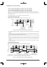
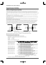
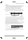
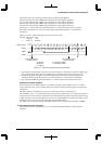
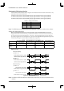
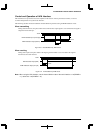
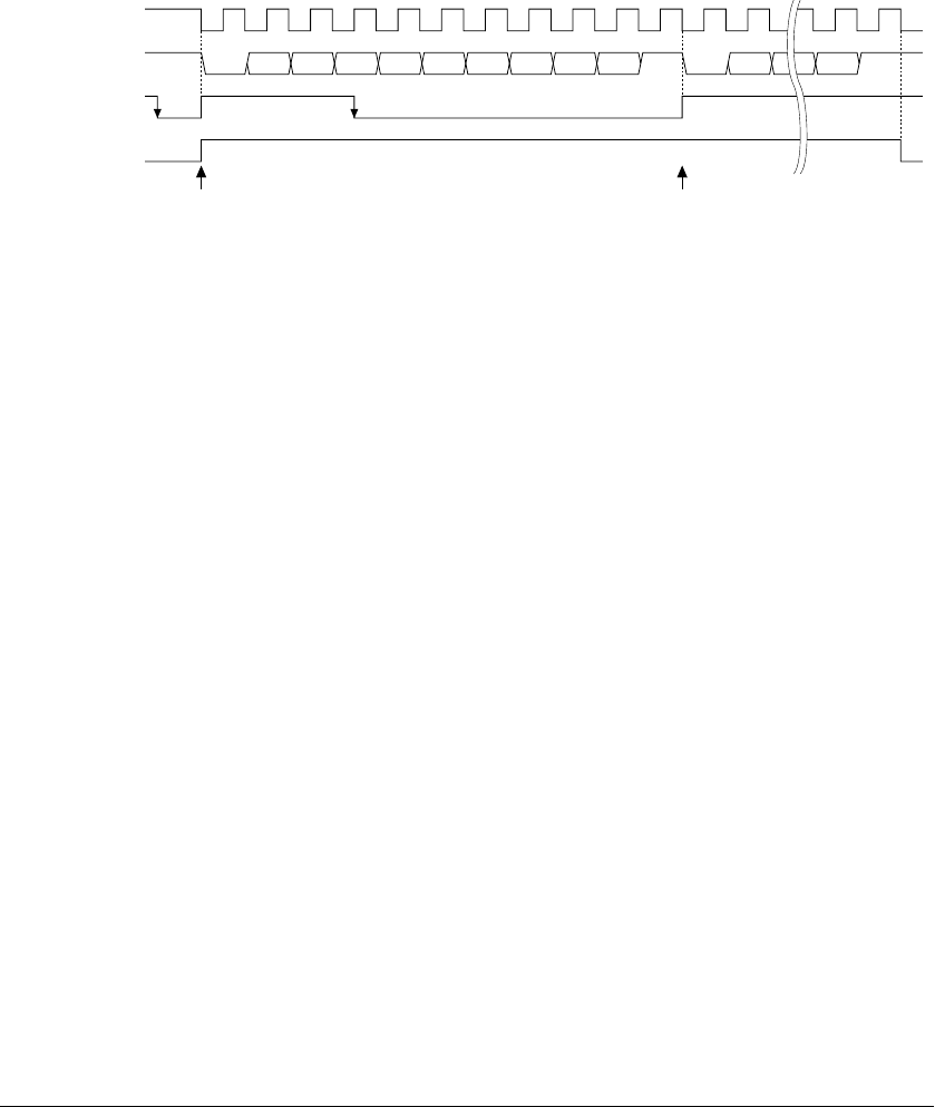
Figure 8.12 shows a transmit timing chart in the asynchronous mode.
Example: Data length 8 bits
Stop bit 1 bit
Parity bit Included
Sampling clock
SOUTx
TDBEx
TENDx
Transmit-buffer empty
interrupt request
Transmit-buffer empty
interrupt request
S1
S2
P
Start bit
Stop bit
Parit
y
bit
A
B
First data is written.
Next data is written.
S1 D0 D1 S1 D0D2 D3 D4 D5 D6 D7 P S2 P S2
AB
Figure 8.12 Transmit Timing Chart in Asynchronous Mode
1. The contents of the data register are transferred to the shift register synchronously with the first falling edge
of the sampling clock. At the same time, the SOUTx pin is setting to a low level to send the start bit.
2. Each bit of data in the shift register is transmitted beginning with the LSB at each falling edge of the
subsequent sampling clock. This operation is repeated until all 8 (or 7) bits of data are transmitted.
3. After sending the MSB, the parity bit (if EPRx = "1") and the stop bit are transmitted insuccession.
• Successive transmit operation
When the data in the transmit data register is transferred to the shift register, TDBEx is reset to "1" (buffer
empty). Once this occurs, the next transmit data can be written to the transmit data register, even during data
transmission.
This allows data to be transmitted successively. The transmit procedure is described above.
When TDBEx is set to "1", a transmit-data empty interrupt factor simultaneously occurs. Since an interrupt can
be generated as set by the interrupt controller, the next transmit data can be written using an interrupt processing
routine. In addition, since this interrupt factor can be used to invoke IDMA, the data prepared in memory can be
transmitted successively to the transmit data register through DMA transfers.
For details on how to control interrupts and IDMA requests, refer to "Serial Interface Interrupts and DMA".
(3) Terminating transmit operations
When data transmission is completed, write "0" to the transmit-enable bit TXENx to disable transmit
operations.