III PERIPHERAL BLOCK: CLOCK TIMER
S1C33210 FUNCTION PART EPSON B-III-7-3
RUN/STOP the clock timer
The clock timer starts counting when "1" is written to TCRUN (D0) / Clock timer Run/Stop register (0x40151)
and stops counting when "0" is written.
When the clock timer is made to RUN, the 256-Hz clock input is enabled at a falling edge of the low-speed
(OSC1) oscillation clock pulse, and the 8-bit binary counter counts up at each falling edge of this 256-Hz clock.
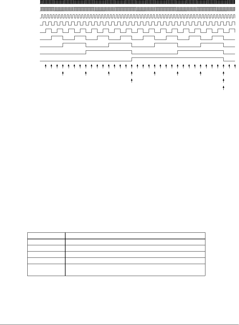
Figure 7.2 shows the operation of the 8-bit binary counter.
256 Hz
128 Hz
64 Hz
32 Hz
16 Hz
8 Hz
4 Hz
2 Hz
1 Hz
32 Hz interrupt
8 Hz interrupt
2 Hz interrupt
1 Hz interrupt
f
OSC1
/128
TCD0
TCD1
TCD2
TCD3
TCD4
TCD5
TCD6
TCD7
Figure 7.2 Timing Chart of 8-Bit Binary Counter
The 8-bit binary counter outputs a 1-Hz signal in its final stage.
The second counter counts the 1-Hz signal thus output. When it counts 60 seconds, the counter outputs a 60-
second signal and is reset to 0 seconds.
Similarly, the minute and hour counters count 60 minutes and 24 hours, respectively, using the signals output
by each preceding counter.
The day counter is a 16-bit binary counter and can count up to 65,536 days using the 24-hour signal output by
the hour counter.
One of the following signals output by each counter can be selected to generate an interrupt:
32 Hz, 8 Hz, 2 Hz, 1 Hz (1 second), 1 minute, 1 hour, 1 day
If "0" is written to TCRUN, the clock timer is stopped at a rising edge of the low-speed (OSC1) oscillation
clock to prevent device malfunction caused by the concurrent termination of counting (falling edge of the
256-Hz clock).
Even when the clock timer is stopped, each counter retains the data set at that point. When the timer is made to
RUN again while in that state, each counter restarts counting from the retained value.
Reading out counter data
The data in each counter can be read out in a software as binary data.
Table 7.2 Reading Out Counter Data
Counter Counter data
1 Hz to 128 Hz TCD[7:0] (D[7:0]) / Clock timer divider register (0x40153)
Second counter TCMD[5:0] (D[5:0]) / Clock timer second counter (0x40154)
Minute counter TCHD[5:0] (D[5:0]) / Clock timer minute counter (0x40155)
Hour counter TCDD[4:0] (D[4:0]) / Clock timer hour counter (0x40156)
Day counter TCND[15:0](D[7:0]) / Clock timer day (high-order) counter (0x40158)
(D[7:0]) / Clock timer day (low-order) counter (0x40157)
Data is read directly from the counter during operation. For this reason, a counter can overflow while reading
data from each counter, so the data thus read may not be exact. For example, if the 8-bit binary counter is read
at 0xFF and then overflows before reading the next seconds counter, the value of the seconds counter is its
count plus the one second that has elapsed since the 8-bit binary counter was read. To prevent this problem,
try reading out each counter several times and make sure data has not been modified.


