


III PERIPHERAL BLOCK: MONITORED MOBILE ACCESS INTERFACES
B-III-10-20 EPSON S1C33210 FUNCTION PART
D. Interrupt source: Idle detect
Condition The signal latched into the idle detect changes from "0" to "1."
To clear Reset E/S INT command
(8) MSINT = Modem status change interrupt
Interrupt source Change in modem status input signals
Condition The RI, CTS, DCD, or DSR input signal changes (either direction).
To clear Write "1" to the corresponding interrupt status bit
Mobile Access Interface Interrupt Outputs
The five mobile access interface interrupt groups (UINT4 to UINT0) are connected to the CPU through port
interrupt request output pins (CP4 to CP0). The communications block interrupt select register provides settings for
mapping all five to a single output, or, at the other extreme, to distribute them to separate outputs.
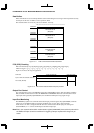
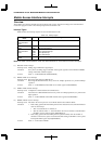
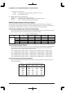
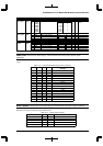
Interrupt Group Assignments for Communications Modes
The communications macro select (MCRS) register (D[1:0]/0x200000) specifies the communications mode and
thus the assignments to the five interface interrupt groups UINT4 to UINT0.
Table 10.9 Interrupt Groups
Communications
mode
Serial interface
Ch. 3
UART
communications
HDLC
communications
PDC
communications
PHS
communications
Interrupt UINT0 ––RXINT PDCINT PRINT
Group UINT1 ––TXINT – PTINT
UINT2 ––SPINT ––
UINT3 ––ESINT ––
UINT4 MSINT MSINT MSINT MSINT MSINT
Interrupt Request Outputs CP[4:0]
The communications block CPx interrupt select registers (CPxEN) (D[4:0]/0x0200020 to D[4:0]/0x0200028)
provide program control over the mapping of the five interface interrupt groups UINT4 to UINT0 to the
interrupt request pins CP4 to CP0 using the following formulas.
CP0 = CP0EN0*UINT0 + CP0EN1*UINT1 + CP0EN2*UINT2 + CP0EN3*UINT3 + CP0EN4*UINT4
CP1 = CP1EN0*UINT0 + CP1EN1*UINT1 + CP1EN2*UINT2 + CP1EN3*UINT3 + CP1EN4*UINT4
CP2 = CP2EN0*UINT0 + CP2EN1*UINT1 + CP2EN2*UINT2 + CP2EN3*UINT3 + CP2EN4*UINT4
CP3 = CP3EN0*UINT0 + CP3EN1*UINT1 + CP3EN2*UINT2 + CP3EN3*UINT3 + CP3EN4*UINT4
CP4 = CP4EN0*UINT0 + CP4EN1*UINT1 + CP4EN2*UINT2 + CP4EN3*UINT3 + CP4EN4*UINT4
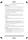
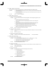
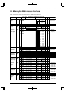
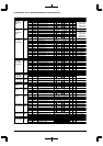
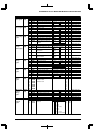
Port Interrupts and Interrupt Request Outputs
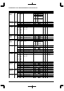
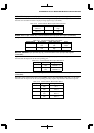
Table 10.10 summarizes the relationships between the above interrupt request outputs CP[4:0] and the port
input interrupts FPT[7:3].
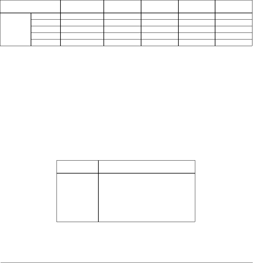
Table 10.10 Port Interrupts and Interrupt Request Outputs
Interrupt SPT setting
source 11 10 01 00
FPT7
FPT6
FPT5
FPT4
FPT3
FPT2
FPT1
FPT0
P27
P26
P25
P24
P23
P22
P21
P20
–
–
P05
P04
P03
P02
P01
P00
P33
P32
P31
–
<CP4>
K52
K51
K50
<CP3>
<CP2>
<CP1>
<CP0>
K63
K62
K61
K60