V DMA BLOCK: HSDMA (High-Speed DMA)
B-V-2-10 EPSON S1C33210 FUNCTION PART
Successive transfer mode
The channel for which DxMOD in control information is set to "01" operates in successive transfer mode. In
this mode, a data transfer is performed by one trigger a number of times as set by the transfer counter. The
transfer counter is decremented to "0" by one transfer executed.
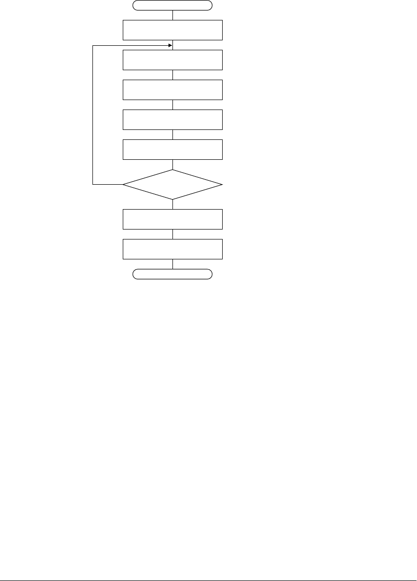
The operation of HSDMA in successive transfer mode is shown by the flow chart in Figure 2.4.
START
END
Transfer counter - 1
Transfer
counter = 0
N
Y
Increments/decrements
address ∗
∗: according to SxIN/DxIN
settings
Data read from source
(1 byte or 1 half word)
Data write to destination
(1 byte or 1 half word)
Clear trigger flag HSx_TF
to accept next trigger
Clear HSDMA enable bit
HSx_EN
Set interrupt factor flag
FHDMx
Figure 2.4 Operation Flow in Successive Transfer Mode
(1) When a trigger is accepted, the trigger flag HSx_TF is cleared and then data of the size set in the control
information is read from the source address.
(2) The read data is written to the destination address.
(3) The addresses are incremented or decremented according to the SxIN/DxIN settings.
(4) The transfer counter is decremented.
(5) Steps (1) to (4) are repeated until the transfer counter reaches 0.
(6) The HSDMA enable bit HSx_EN is cleared and HSDMA interrupt factor flag in ITC is set when the
transfer counter reaches 0 (when DINTENx = "1").


