


III PERIPHERAL BLOCK: SERIAL INTERFACE
B-III-8-6 EPSON S1C33210 FUNCTION PART
RLD =
f
PSCIN × pdr
- 1 (Eq. 1)
2 × bps
RLD: Reload data register setup value of the 8-bit programmable timer
f
PSCIN: Prescaler input clock frequency (Hz)
bps: Transfer rate (bits/second)
pdr: Division ratio of the prescaler
Note: The division ratios selected by the prescaler differ between 8-bit programmable timers 2 and 3, so
be careful when setting the ratio.
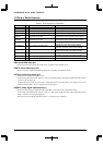
8-bit programmable timer 2, 4: 1/2, 1/4, 1/8, 1/16, 1/32, 1/64, 1/2048, 1/4096
8-bit programmable timer 3, 5: 1/2, 1/4, 1/8, 1/16, 1/32, 1/64, 1/128, 1/256
For details on how to control the prescaler and 8-bit programmable timers, refer to "Prescaler", and "8-Bit
Programmable Timers".
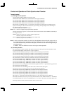
The serial-interface control register contains an SSCKx bit to select the clock source used for the asynchronous
mode. Although this bit does not affect the clock in the clock-synchronized mode, its content becomes
indeterminate at initial reset. Therefore, be sure to initialize this bit by writing "0" (Internal clock), even when
using the serial interface in the clock-synchronized master mode.
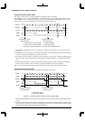
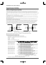
• Clock-synchronized slave mode
This mode operates using the clock that is output by the external master. This clock is input from the #SCLK
pin.
Therefore, there is no need to control the prescaler or 8-bit programmable timer.
Initialize SSCKx by writing "1" (#SCLKx).
Note: SSCK11 and SSCK31 must be "0" because Ch. 1 and Ch. 3 support only asynchronous operation.