III PERIPHERAL BLOCK: SERIAL INTERFACE
B-III-8-12 EPSON S1C33210 FUNCTION PART
Asynchronous Interface
Outline of Asynchronous Interface
Asynchronous transfers are performed by adding a start bit and a stop bit to the start and end points of each serial-
converted data. With this method, there is no need to use a clock that is fully synchronized on the transmit and
receive sides; instead, transfer operations are timed by the start and stop bits added to the start and end points of each
data.
In the 8-bit asynchronous mode (SMDx[1:0] = "11"), 8 bits of data can be transferred; in the 7-bit asynchronous
mode (SMDx[1:0] = "10"), 7 bits of data can be transferred.
In either mode, it is possible to select the stop-bit length, add a parity bit, and choose between even and odd parity.
The start bit is fixed at "1".
The operating clock can be selected between an internal clock generated by an 8-bit programmable timer or an
external clock that is input from the #SCLKx pin.
Since the transmit and receive units are both constructed with a double-buffer structure, successive transmit and
receive operations are possible. Furthermore, since the transmit and receive units are independent, full-duplex
communication in which transmit and receive operations are performed simultaneously is also possible.
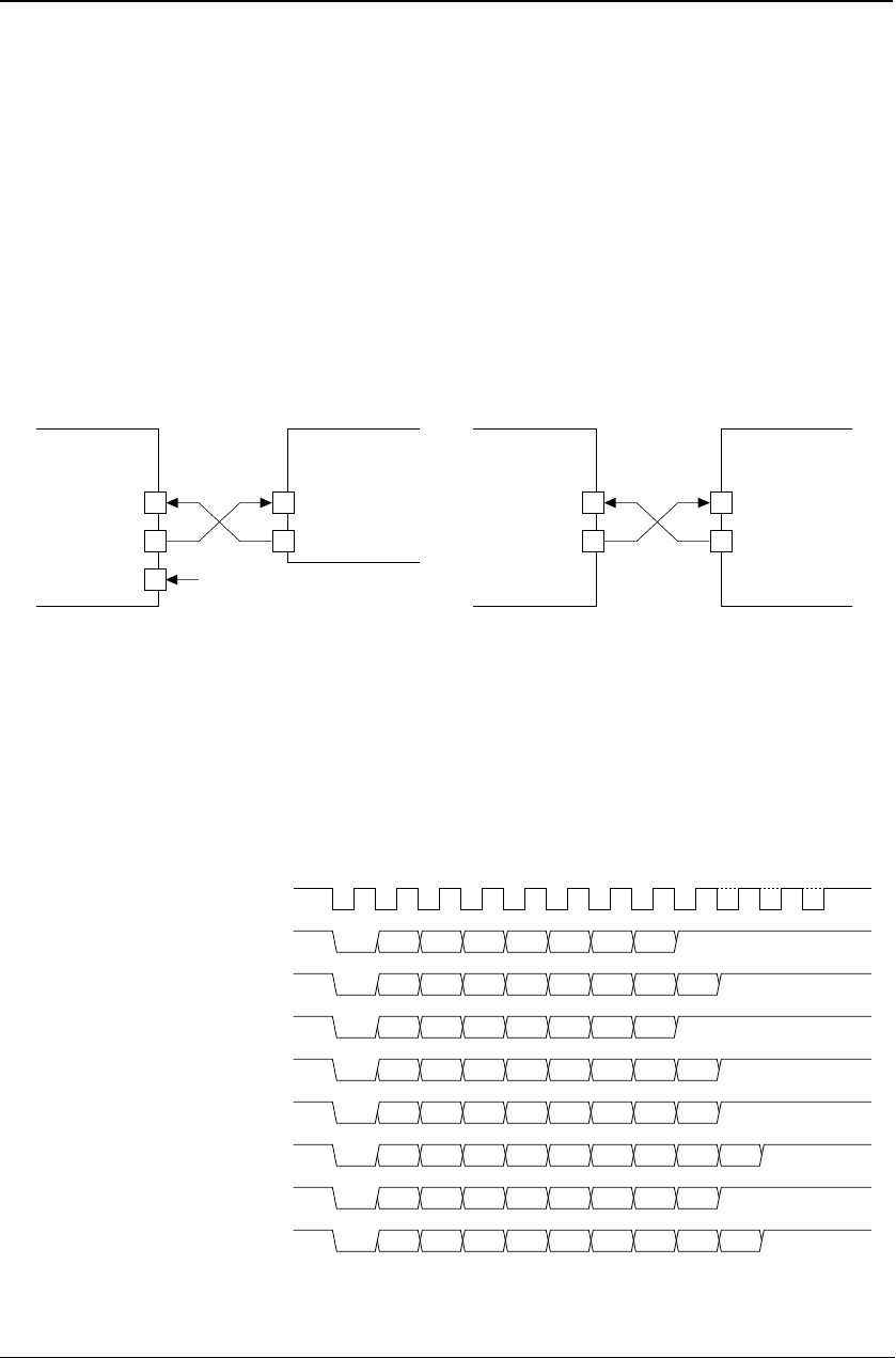
Figure 8.8 shows an example of how input/output pins are connected for transfers in the asynchronous mode.
Data input
Data output
External clock
SINx
SOUTx
#SCLKx
SINx
SOUTx
External
serial device
(
1
)
When external clock is used
(
2
)
When internal clock is used
S1C33
Data input
Data output
External
serial device
S1C33
Figure 8.8 Example of Connection in Asynchronous Mode
When the asynchronous mode is selected, it is possible to use the IrDA interface function.
Asynchronous-transfer data format
The data format for asynchronous transfer is shown below.
Data length: 7 or 8 bits (determined by the selected transfer mode)
Start bit: 1 bit, fixed
Stop bit: 1 or 2 bits
Parity bit: Even or odd parity, or none
Sampling clock (for transmitting)
s1: start bit, s2 & s3: stop bit, p: parity bit
7-bit asynchronous mode
(Stop bit: 1 bit, parity: none)
s1 D0 D1 D2 D3 D4 D5 D6 s2
(Stop bit: 1 bit, parity: used)
s1 D0 D1 D2 D3 D4 D5 D6 p s2
(Stop bit: 2 bits, parity: none)
s1 D0 D1 D2 D3 D4 D5 D6 s2 s3
(Stop bit: 2 bits, parity: used)
s1 D0 D1 D2 D3 D4 D5 D6 p s2 s3
8-bit asynchronous mode
(Stop bit: 1 bit, parity: none)
s1 D0 D1 D2 D3 D4 D5 D6 D7 s2
(Stop bit: 1 bit, parity: used)
s1 D0 D1 D2 D3 D4 D5 D6 D7 p s2
(Stop bit: 2 bits, parity: non)
s1 D0 D1 D2 D3 D4 D5 D6 D7 s2 s3
(Stop bit: 2 bits, parity: used)
s1 D0 D1 D2 D3 D4 D5 D6 D7 p s2 s3
Figure 8.9 Data Format for Asynchronous Transfer
Serial data is transmitted and received, starting with the LSB.


