


III PERIPHERAL BLOCK: SERIAL INTERFACE
B-III-8-14 EPSON S1C33210 FUNCTION PART
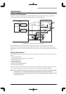
Any desired clock frequency can be obtained by setting the prescaler division ratio and the reload data of the
8-bit programmable timer as necessary. The relationship between the contents of these setting and the transfer
rate is expressed by Eq. 2.
The 8-bit programmable timer has its underflow signal further divided by 2 internally, in order to ensure that
the duty ratio of the clock supplied to the serial interface is 50%.
Furthermore, the clock output by the 8-bit programmable timer is divided by 16 or 8 internally in the serial
interface, in order to create a sampling clock (refer to "Sampling clock"). This division ratio must also be
considered when setting the transfer rate.
These division ratios are taken into account in Eq. 2.
RLD =
f
PSCIN × pdr × sdr
- 1 (Eq. 2)
2 × bps
RLD: Set value of the 8-bit programmable timer's reload data register
f
PSCIN: Prescaler input clock frequency (Hz)
bps: Transfer rate (bits/second)
pdr: Division ratio of the prescaler
sdr: Internal division ratio of the serial interface (1/16 or 1/8)
Note: The division ratio selected using the prescaler differs between 8-bit programmable timers 2 and 3.
Take this into account when setting a division ratio.
8-bit programmable timer 2, 4: 1/2, 1/4, 1/8, 1/16, 1/32, 1/64, 1/2048, 1/4096
8-bit programmable timer 3, 5: 1/2, 1/4, 1/8, 1/16, 1/32, 1/64, 1/128, 1/256
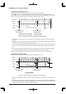
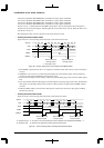
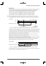
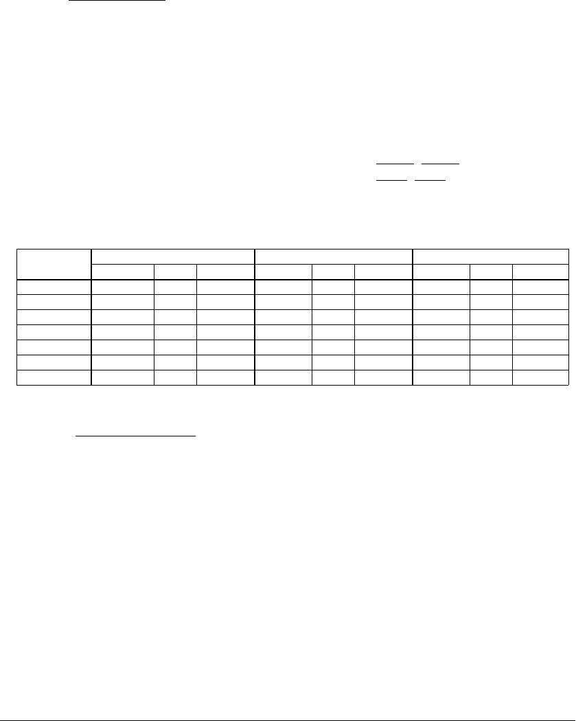
Table 8.4 shows examples of prescaler division ratios and the reload data settings of the programmable timer, in
cases in which the internal division ratio of the serial interface is set to 1/16.
Table 8.4 Example of Transfer Rate Settings
Transfer rate fPSCIN = 20 MHz fPSCIN = 25 MHz fPSCIN = 33 MHz
(bps) RLD pdr Error (%) RLD pdr Error (%) RLD pdr Error (%)
300 129 1/16 0.16025 162 1/16 -0.14698 216 1/16 0.00640
1200 129 1/4 0.16025 162 1/4 -0.14698 216 1/4 0.00640
2400 129 1/2 0.16025 162 1/2 -0.14698 216 1/2 0.00640
4800 64 1/2 0.16025 80 1/2 -0.46939 108 1/2 -0.45234
9600 32 1/2 -1.35732 40 1/2 -0.75584 53 1/2 0.46939
14400 21 1/2 -1.35732 13 1/4 -3.11880 35 1/2 0.46939
28800 10 1/2 -1.35732 13 1/2 -3.11880 17 1/2 0.46939
Make sure the error is within 1%. Calculate the error using the following equation:
Error = {
f
PSCIN × pdr
-1 } × 100 [%]
(RLD + 1) × 32 × bps
For details on how to control the prescaler and 8-bit programmable timers, refer to "Prescaler" and "8-Bit
Programmable Timers".
• External clock
When an external clock is selected, the serial interface is clocked by a clock input from the #SCLKx pin.
Therefore, there is no need to control the prescaler and 8-bit programmable timers.
Any desired clock frequency can be set. The clock input from the #SCLKx pin is internally divided by 16 or 8 in
the serial interface, in order to create a sampling clock (refer to "Sampling clock"). This division ratio must also
be considered when setting the transfer rate.