


TMPR3901F
211
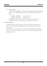
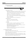
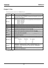
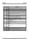
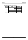
2.4.3 Register address map
Seven registers associated with the memory protection scheme are mapped in from the kernel memory
space. Table 2-1 shows the addresses of these registers.
Table 2-1. Address protection unit control register addresses
Register Virtual address
BSts 0xFF00 0010
BAddr0 0xFF00 0020
Bcnt0 0xFF00 0024
BMsk0 0xFF00 0028
BAddr1 0xFF00 0030
Bcnt1 0xFF00 0034
BMsk1 0xFF00 0038
2.5 Debug Support Unit
This unit supports an external real-time debug system. It includes a hardware break and other functions. The
TMPR3901F has eight signals for this purpose. These signals should be left open when the real-time debug
system is not used.
2.6 Synchronizer
This unit synchronizes the reset input signal, interrupt input signal and coprocessor condition branch signal
with the processor clock.
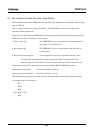
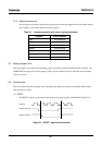
(1) RESET
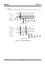
The RESET* signal is synchronized with the processor clock in phase with SYSCLK (Figure 2-3).
Figure 2-3 RESET* signal synchronization
SYSCLK
RESET*(external)
RESET*(internal)