


Architecture
56
(5) NmI (Non-maskable Interrupt)
This bit is set to 1 when a non-maskable interrupt is raised by the falling edge of the non-
maskable interrupt signal. The bit is cleared to 0 by writing a 1 to it or when a Reset
exception is raised.
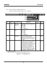
(6) IntMask (Interrupt Mask)
The IntMask bits separately enable or mask each of six hardware and two software interrupts.
Clearing a corresponding bit to 0 masks an interrupt, and setting it to 1 enables the interrupt.
Note that clearing the IEo/IEp/IEc interrupt enable bits, explained below, has the effect of
masking all interrupts.
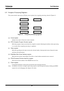
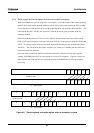
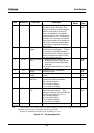
(7) KUc/KUp/KUo (Kernel/User mode: current/previous/old)
The three bits KUc/KUp/KUo form a three-level stack, indicating the current, previous and
old operating modes. For each bit, 0 indicates kernel mode and 1 is user mode. The way
these bits are manipulated and used in exception processing is explained in 6.2.5 below. KUc
is cleared to 0 when exception raises.
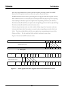
(8) IEc/IEp/IEo (Interrupt Enable: current/previous/old)
The three bits IEc/IEp/IEo form a three-level stack, indicating the current, previous and old
interrupt enable status. For each bit, 0 means interrupts are disabled, and 1 means interrupts
are enabled. The way these bits are manipulated and used in exception processing is
explained in 6.2.5 below. IEc is cleared to 0 when exception raises.