


TMPR3901F
217
Chapter 4 Operations
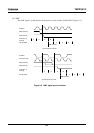
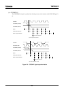
This chapter shows TMPR3901F bus operations and timing.
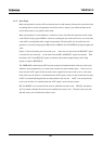
All TMPR3901F bus operations are synchronized with the rising edge of SYSCLK.
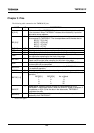
The bus operation pin states are as follows when no bus operations are being performed.
A [31:2] undefined
D [31:0] high impedance
BE [3:0]*
H
RD*, WR*
H
LAST*
H
BSTART*
H
BURST*
H
BSTSZ [1:0] undefined
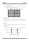
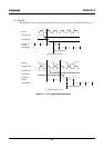
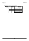
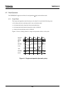
4.1 Clock
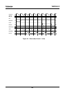
The TMPR3901F can control the clock frequency to reduce power dissipation and to simplify system design.
• Master Clock
This is the base clock of the TMPR3901F. It operates at quadruple the frequency of the crystal oscillator.
FCLK outputs the master clock signal.
• Processor Clock
This is the clock of the R3900 Processor Core. The processor clock runs at 1/1, 1/2, 1/4 or 1/8 the frequency
of the master clock accordingt to the value in the Config register RF field. Running the processor clock at
1/2, 1/4 or 1/8 the frequency of the master clock enables TMPR3901F low power dissipation (reduced
frequency mode).
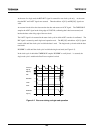
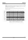
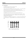
• System Clock
This is the base clock of TMPR3901F bus operations. The system clock is derived from processor clock.
The system clock can be switched to half frequency with the HALF* signal (half-speed bus mode).