


3–44
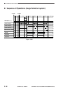
OPERATIONS AND TIMING
COPYRIGHT
©
1998 CANON INC. CANON NP6621 REV.0 FEB. 1998 PRINTED IN JAPAN (IMPRIME AU JAPON)
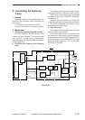
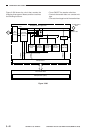
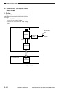
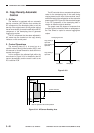
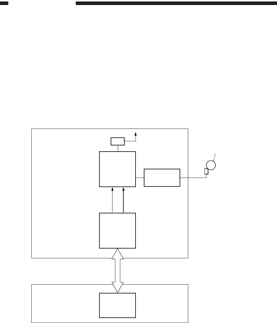
F. Controlling the Static Elimi-
nator Bias
1. Outline
Figure 3-307 show the circuit that controls the
static eliminator bias, and the circuit has the following
functions:
• Turns ON/OFF the static eliminator bias and
controls it to a constant voltage.
• Switches the static eliminator bias voltage
level.
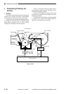
Figure 3-307
Composite power supply PCB
JLVCTL JCTL
Microprocessor
J5
J307
Q301
Microprocessor
Static eliminator
bias drive
circuit
T4
24V
Transformer
circuit
DC controller PCB
Photosensitive
drum
Static
eliminator