4–40
COPYRIGHT
©
1998 CANON INC. CANON NP6621 REV.0 FEB. 1998 PRINTED IN JAPAN (IMPRIME AU JAPON)
MECHANICAL SYSTEM
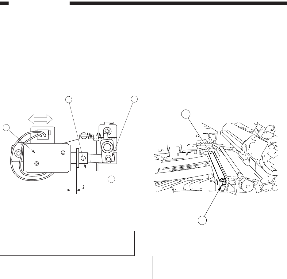
3. Positioning the Primary Charging
Roller Cleaning Solenoid
Loosen the two screws used to fix the solenoid
e in place and move the solenoid e in the the
direction of arrow B so that the distance l in Figure
4-507 is 5.5 ±0.2 mm when the joint q is butted
against a of the solenoid support plate w.
Figure 4-507
Caution:
You must always make this adjustment when-
ever you have replaced the solenoid.
B
C. Transfer Charging Assem-
bly
1. Removing the Transfer Roller
1) Open the front door.
2) Open the top body.
3) Remove the static eliminator.
4) Remove the bushing q, and remove the trans-
fer roller w by lifting it.
Figure 4-508
Caution:
Do not touch the surface of the roller.
Do not soil the surface of the roller.
2
1
a
= 5.5 ± 0.2
2
1
3


