


3–8
OPERATIONS AND TIMING
COPYRIGHT
©
1998 CANON INC. CANON NP6621 REV.0 FEB. 1998 PRINTED IN JAPAN (IMPRIME AU JAPON)
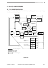
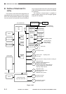
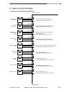
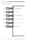
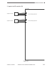
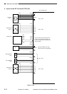
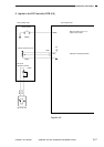
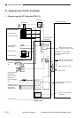
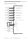
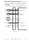
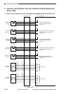
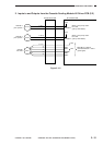
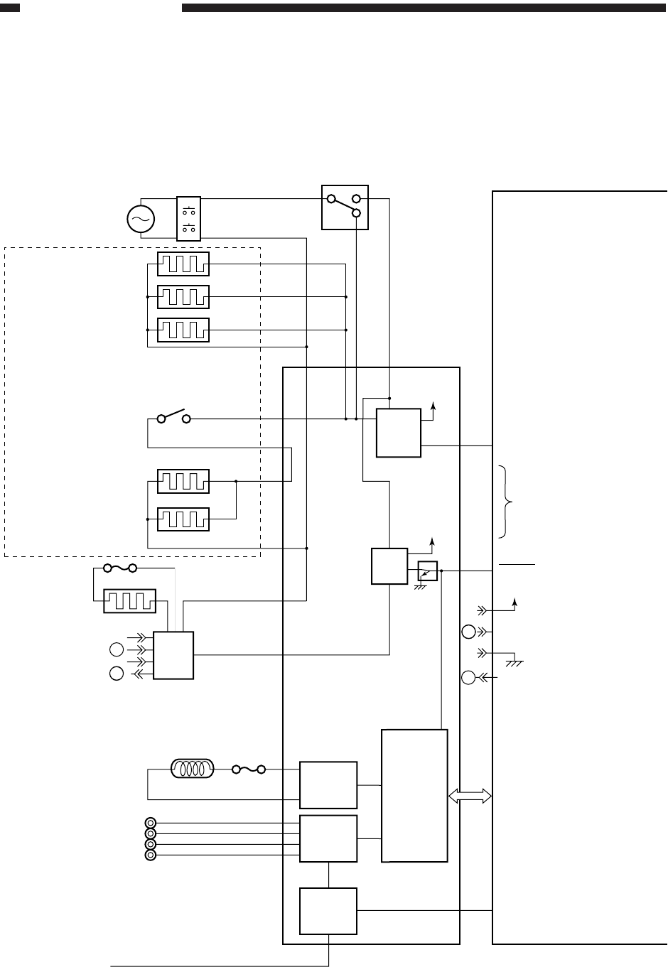
D. Outputs from the DC Controller
1. Outputs from the DC Controller PCB (1/5)
Figure 3-108
+5V
24V
+5V
A
B
B
RL101
RL103
HTON*
TEP*
EHTRL*
Cassette heater (H4)
Drum heater (H3)
Cassette heater (H5)
Anti-condensation
switch (SW1)
Lens heater (R1)
Lens heater (R2)
Fuse (FU1)
Fixing heater
(H1)
Fluorescent heater
switch (SW2)
Fluorescent lamp
heater (H2)
Fluorescent lamp
(LA1)
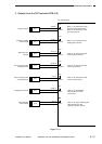
Primary charging roller
Developing cylinder
Transfer roller
Static eliminator
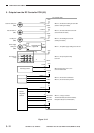
Door switch
Main switch
ON
Fixing
heater
driver
Scanning
lamp control
circuit
High-voltage
circuit
Toner level
detection
sensor
Antenna Sensor
Composite power
supply PCB
Microprocessor
DC controller PCB
When '0' RL101 turns ON.
(ON when the power is OFF)
When RL101 is ON and SW1
is ON, the heater (R1, R2)
turns ON.
When '0', RL103 turns ON.
(ON when the power is ON)
When the heater is ON, '0'.
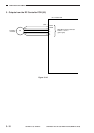
Communicates with the composite
power supply PCB.
When '0', "ADD TONER"
is indicated.
J319
–4
–1
–2
–3
HTRD See p. 3-89.
A
ACOFF