


3–33
OPERATIONS AND TIMING
COPYRIGHT
©
1998 CANON INC. CANON NP6621 REV.0 FEB. 1998 PRINTED IN JAPAN (IMPRIME AU JAPON)
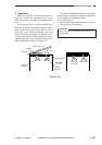
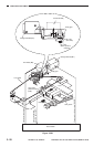
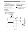
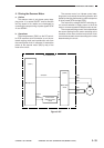
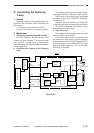
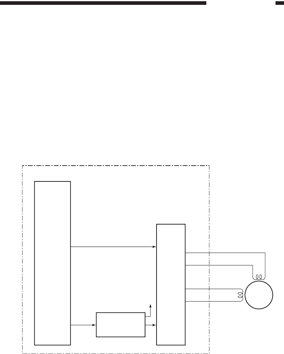
4. Driving the Scanner Motor
a. Outline
The scanner motor is a 4-phase control step-
ping motor. It is turned ON/OFF and its direction
and the speed of its rotation are chanceged by
controlling the output timing of pulse signals SCA/
A* and SCB/B*.
b. Operations
The microprocessor (Q301) on the DC control-
ler PCB receives such information as on the se-
lected copying mode and reproduction ratio from
the control panel circuit. In response, it issues drive
pulses to the scanner motor (M2) by way of the
motor drive circuit.
The scanner motor is a 4-phase control step-
ping motor and controls the scanning direction and
speed by changing the frequency and the sequence
of drive pulses (SCA through SCB*).
The motor drive voltage ON/OFF switching cir-
cuit controls whether to apply power to drive the
motor or to remove power to keep the motor at rest.
The current switching control circuit determines
the current flowing into the motor according to the
revolution of the motor, and the motor driver circuit
controls the constant current according to the value
determined by the circuit.
Figure 3-207
(Q301)
(Q324)
J302
SCA
SCA*
SCB
SCB*
M2
5V
A,A*,B,B*
Microprocessor
DC controller PCB
Current
value
switching
Current value
switching control
circuit
Motor driver
circuit