


3–103
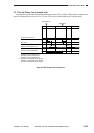
OPERATIONS AND TIMING
COPYRIGHT
©
1998 CANON INC. CANON NP6621 REV.0 FEB. 1998 PRINTED IN JAPAN (IMPRIME AU JAPON)
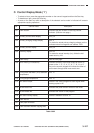
C. Detecting Errors on the
Power Supply PCB
The microprocessor (U402) and LED501 on the
composite power supply PCB checks for errors; if
an error is identified, the microprocessor (U402)
communicates with the DC controller to indicate the
results of self diagnosis on the display or to flash
LED501 to alert the user.
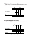
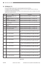
• Communication Error between DC Controller
PCB and Composite Power Supply PCB
If an error occurs in the communication between
the DC controller PCB and the composite power
supply PCB, ‘E240’ is indicated as soon as the DC
controller PCB identifies an error. In addition, LED
is flashed at intervals of 5 sec when the composite
power supply PCB identifies an error.
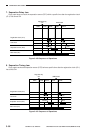
• Data Error in the High-Voltage Output
If the difference between the actual control
value and the setting associated with the high
voltage generated by the microprocessor (U402) is
more than a specific value, the microprocessor
(U402) communicates error data to the DC controller
PCB to indicate ‘E064’.
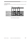
• Detecting Overcurrent in the Low-Voltage
Power Supply
If the composite power supply PCB identifies an
error in any of the DC loads or overcurrent caused
by wire trapping, the LED is on fixed.