


3–34
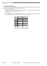
OPERATIONS AND TIMING
COPYRIGHT
©
1998 CANON INC. CANON NP6621 REV.0 FEB. 1998 PRINTED IN JAPAN (IMPRIME AU JAPON)
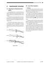
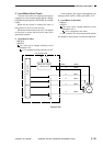
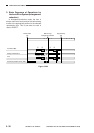
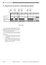
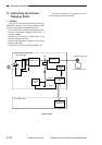
D. Operations of the Scanner in Page Separation Mode
Figure 3-208
I, II, and II in Figure 3-208 use the scanner home
position signal (falling edge of SCHP) for the 1st
page as the reference for control by the micropro-
cessor on the DC controller PCB.
The microprocessor determines how much the
scanner must travel forward to suit the selected
cassette size.
I, II: The distance traveled forward is determined
by the selected reproduction ratio and the
cassette size.
III: If the forward travel distance during II of
Figure 3-208 is in excess of about 216 mm,
216 mm is used to represent the leading
edge of the second page.
*Non-AE, page separation mode, A4, 2 copies, continuous.
Scanner home position
signal (PS1)
Scanning lamp (LA1)
Scanner
Original
leading
edge of
1st page
Original
leading
edge of
1st page
Original
leading
edge of
1st page
Original
leading
edge of
2nd page
Original
leading
edge of
1st page
Original
leading
edge of
2nd page
Forward
Reverse
I I II III II III
SCFW1
INTR
SCFW1
SCRVI SCRVI
SCFW2 SCRV2 SCFW2 SCRV2 LSTR