


4–50
COPYRIGHT
©
1998 CANON INC. CANON NP6621 REV.0 FEB. 1998 PRINTED IN JAPAN (IMPRIME AU JAPON)
MECHANICAL SYSTEM
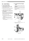
B. Composite Power Supply
PCB
1. Removing the Composite Power Sup-
ply PCB
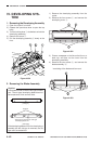
1) Remove the lower rear cover and the left cover.
2) Disconnect all connectors of the composite
power supply PCB.
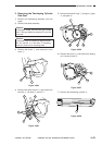
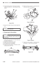
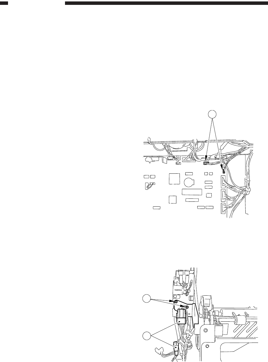
3) Disconnect J317 and J322 q of the DC control-
ler PCB.
Figure 4-801
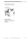
4) Disconnect the two AC connectors w, and
remove the two screws e.
Figure 4-802
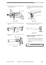
VIII. ELECTRICAL
A. DC Controller PCB
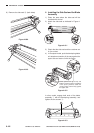
1. Removing the DC Controller PCB
1) Remove the lower rear cover.
2) Disconnect the connector from the DC controller.
3) Remove the six screws, and remove the DC
controller PCB from the mounting plate.
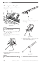
2. Points to Note When Replacing the
DC Controller
• When sending the DC controller PCB to the
workshop or the factory, put it in a static conduc-
tive bag. Use a static conductive bag whose that
is transparent enough in order for the face of the
DC controller PCB to be visible.
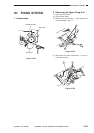
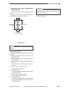
After replacement, perform the following:
q enter the settings recorded on the service
mode label
w adjust the multifeeder paper width sensor
e adjust the scanning lamp light intensity
r adjust AE
t enter the values recorded on the composite
power supply label
1
3
2