


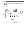


5–30
INSTALLATION
COPYRIGHT
©
1998 CANON INC. CANON NP6621 REV.0 FEB. 1998 PRINTED IN JAPAN (IMPRIME AU JAPON)
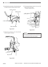
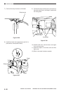
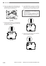
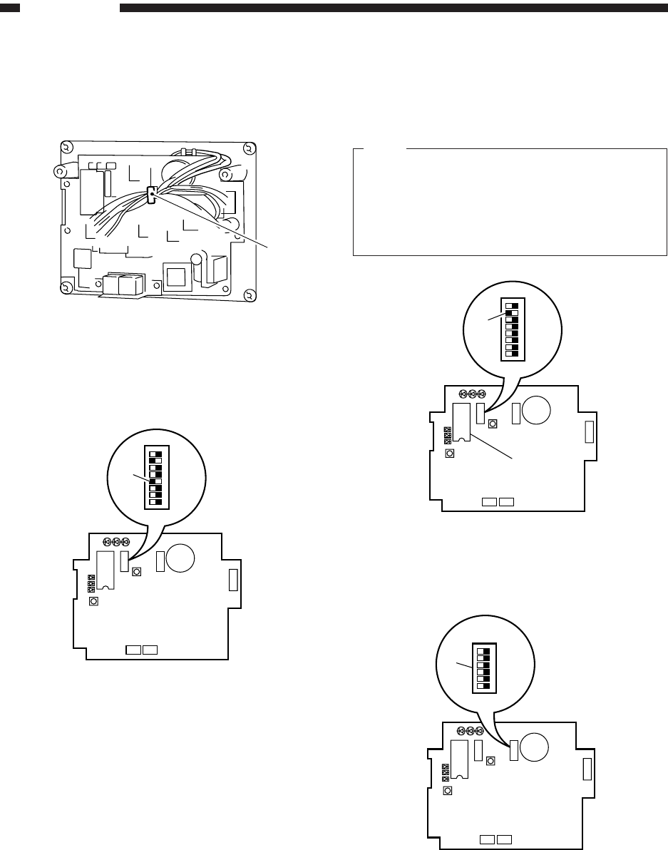
6) Remove the slack from the cable between the
copier and the RDD; keep the excess cable to
the RDD using the harness band !0.
Fig. 5-808
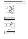
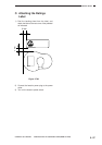
7) Shift bit 4 of the DIP switch 2 !1 to ON so that the
communication mode between the RDD and
the copier is IPC mode.
Fig. 5-809
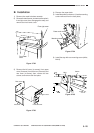
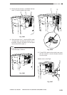
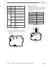
8) If the ROM IC6 !222 is mounted on the RDD’s
PCB, shift bit 7 of the DIP switch 2 !3 to ON;
otherwise, shift bit 7 of the DIP switch 2 to OFF.
Note:
1. If the ROM (IC6; !2) is not mounted, you
need not mount it.
2. If you are mounting or replacing the ROM
(IC6; !2 for upgrading the RDD, be sure to
shift bit 7 of the DIP switch 2 !3 to ON.
Fig. 5-810
9) Set the bits of the DIP switch 3 !4 on the RDD’s
PCB as indicated in the table.
Fig. 5-811
!0
LED1LED2 LED3
2
1
LED5
LED6
LED4
IC6
SW1
SW4
SW3
6
1
BAT1
CN4
1
2
CN3 CN2
12345678
!1
SW2
LED1LED2 LED3
2
1
LED5
LED6
LED4
IC6
SW1
SW4
SW3
6
1
BAT1
CN4
1
2
CN3 CN2
SW2
123456
!4
LED1LED2 LED3
2
1
LED5
LED6
LED4
IC6
SW1
SW4
SW3
6
1
BAT1
CN4
1
2
CN3 CN2
12345678
SW2
!3
!2