


3–48
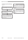
OPERATIONS AND TIMING
COPYRIGHT
©
1998 CANON INC. CANON NP6621 REV.0 FEB. 1998 PRINTED IN JAPAN (IMPRIME AU JAPON)
H. Copy Density Automatic
Control
1. Outline
The machine is equipped with an automatic
density correction (AE) function that controls the
DC component of the developing bias to suit the
density of the original used. As long as the original
has an even density, the machine will adjust the DC
component of the developing bias to generate
fogging-free copies.
The DC component that has been adjusted in
AE mode may be checked on the copy density
indicator on the control panel.
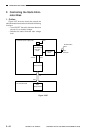
2. Control Operations
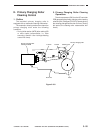
The scanning lamp (FL1) is turned on at a
specific intensity during initial rotation (INTR), and
the scanner is moved forward for about 65 mm to
expose the original.
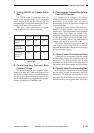
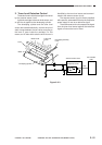
In this condition, the reflected light within the
area shown in Figure 3-311 is checked by the AE
sensor (photodiode), and the result is sent to the
DC controller PCB.
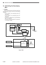
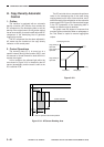
The DC controller in turn computes the optimum
value for the developing bias to be used during
copying based on the input it has received, and it
sends the result of the computation to the composite
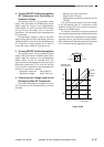
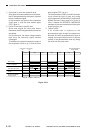
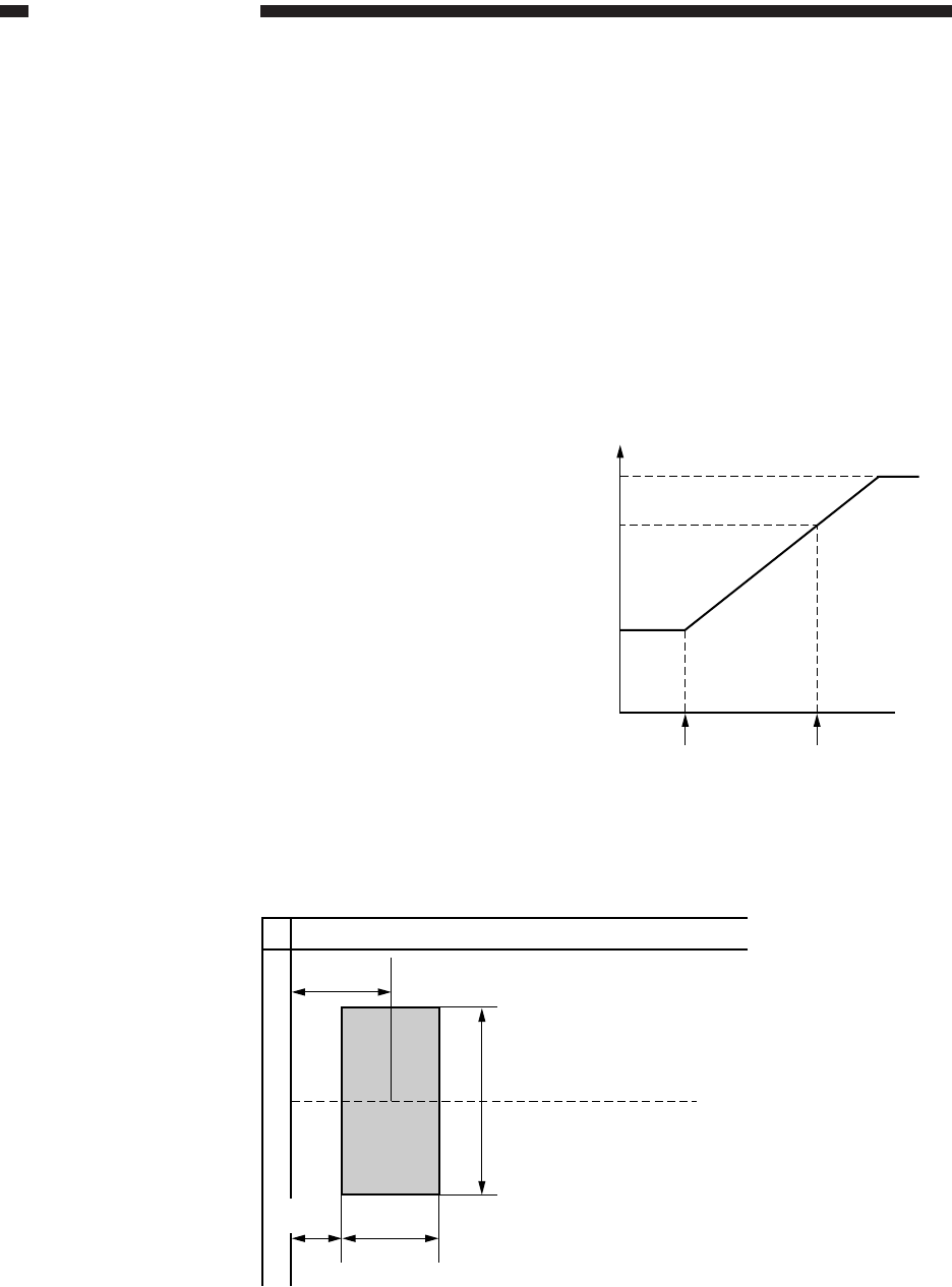
power supply PCB. Figure 3-310 shows the changes
in the DC component of the developing bias in
relation to different original densities.
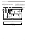
The graph uses the degree of exposure that
provides optimum densities when a newspaper or
the Test Sheet is copied to ensure fogging-free
copies.
Developing DC bias
Copy density 9
equivalent
Copy density 7.5
equivalent
Copy density 5
equivalent
Test Sheet Newspaper
Original density
Figure 3-310
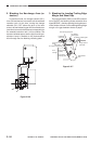
27 mm
(approx.)
Center reference
50 mm (approx.)
A
14 mm
(approx.)
27 mm
(approx.)
Note: A represents the sensor position.
Figure 3-311 AE Sensor Reading Area