


3–39
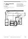
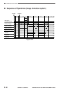
OPERATIONS AND TIMING
COPYRIGHT
©
1998 CANON INC. CANON NP6621 REV.0 FEB. 1998 PRINTED IN JAPAN (IMPRIME AU JAPON)
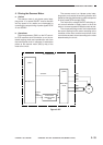
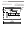
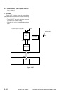
2. Turning ON/OFF the Primary Charg-
ing Roller Bias
Under the control of the microprocessor master
(Q301) on the DC controller PCB, the micro-pro-
cessor on the composite power supply PCB gener-
ates the PCTRLS signal (pulse signal), which causes
the secondary side of the transformer (T4) to go ON
and the primary charging roller bias to be applied.
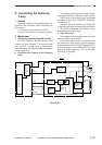
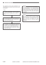
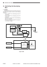
3. Controlling the Primary Charging
Roller Bias to a Constant Voltage
The microprocessor on the composite power
supply PCB reads the PDCS signal (analog signal)
from the voltage detection circuit while the bias
voltage is being applied to the primary charging
roller and controls the PDCPWM signal so that the
output voltage remains constant.
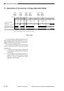
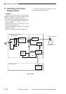
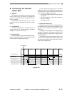
4. Switching the Application Voltage
Level for the Primary Charging Roller
Bias
The machine applies a cleaning bias to the
transfer roller during initial rotation (INTR), when
the scanner is moving in reverse (SCRV), during
last rotation, and at power-on after a jam. (See p. 3-
46.)
To improve the efficiency of cleaning by the
cleaning bias and to prevent residual memory on
the drum by the cleaning bias, the primary charging
roller bias is applied during initial rotation and while
the scanner is moving in reverse.
5. Automatic Correction of the Applica-
tion Voltage Level of the Primary
Charging Roller Bias and the Scan-
ning Lamp ON Voltage Level (APVC,
ALVC control)
Changes in latent static images can affect the
copy quality; such changes in latent static images
result from
• changes in the drum sensitivity, and
• changes in the charges from the primary
charging roller.
On the other hand, these changes occur because
of the site of installation (temperature, humidity),
deterioration of related parts, wear, or dirt.
The machine’s light area potential (V
L) and dark
area potential (V
D) tend to increase. To correct such
an increase, the machine corrects the application
voltage level of the primary charging roller (APVC
control) and, at the same time, corrects the scanning
lamp ON voltage level (ALVC control), thereby
ensuring a specific degree of light area potential
(V
L) and light area potential (VD) at all times.