5–33
INSTALLATION
COPYRIGHT
©
1998 CANON INC. CANON NP6621 REV.0 FEB. 1998 PRINTED IN JAPAN (IMPRIME AU JAPON)
16) Call up the service station to check if the initial
settings have been successfully made; if the
attempt has failed, reset the RAM once again
starting with step 11) through 13).
Important:
You must confirm that the RDD’s settings are
correct by calling the service station.
17) Check that you can place a telephone call from
the RDD to the computer in the service station.
Press the push switch 4 !7. LED6 @3 (red)
should come on; it will go out when transmis-
sion ends successfully, or will start to flash if
transmission fails.
Retransmission is executed in response to a
press on the push switch 4 !7 while LED6 @3 is
flashing.
Transmission is canceled in response to a
press on the push switch 1 @4 while LED6 @3 is
flashing.
Fig. 5-818
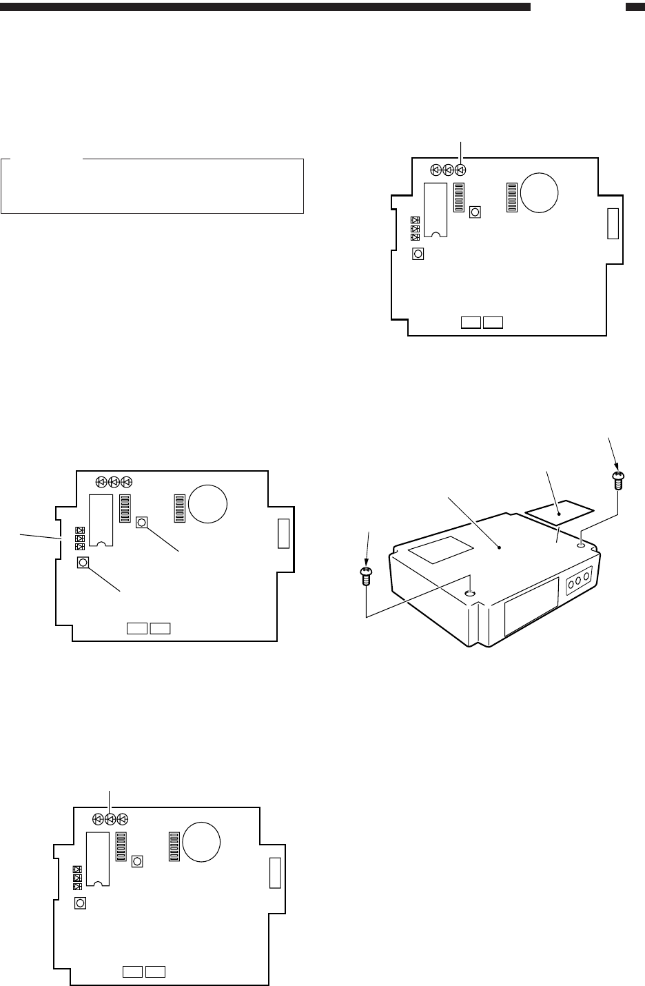
18) Check that the communications between the
RDD and the copier are executed normally.
Connect the copier’s power plug, and switch it
on to make sure that LED 2 @5 (orange) flashes.
Fig. 5-819
19) Press the copier’ COPY START key to make
sure that LED3 @6 (pink) flashes each time a
copy is delivered.
Fig. 5-820
20) Attach the Switch setting label @7, to the RDD’s
top cover q; then, record the setting of each
switch on the label.
Fig. 5-821
21) Fix the RDD’s top cover q in place using two
screws w. (Make sure that the Power Unit’s
cable is fixed in place on the cable guide inside
the RDD and is not trapped by the top cover q.
LED1 LED2 LED3
2
1
LED5
LED6
LED4
IC6
SW1
SW4
SW3
6
1
BAT1
CN4
1
2
CN3 CN2
SW2
@4
!7
@3
@5
LED1 LED2 LED3
2
1
LED5
LED6
LED4
IC6
SW1
SW4
SW3
6
1
BAT1
CN4
1
2
CN3 CN2
SW2
LED1 LED2 LED3
2
1
LED5
LED6
LED4
IC6
SW1
SW4
SW3
6
1
BAT1
CN4
1
2
CN3 CN2
SW2
@6
q
w
w
@7


