


3–40
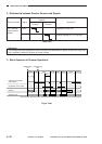
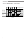
OPERATIONS AND TIMING
COPYRIGHT
©
1998 CANON INC. CANON NP6621 REV.0 FEB. 1998 PRINTED IN JAPAN (IMPRIME AU JAPON)
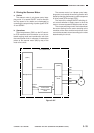
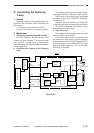
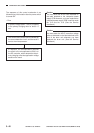
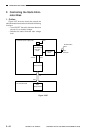
The sequence of this control mechanism is as
follows during initial rotation after the power switch
is turned ON:
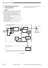
• Flow
A specific voltage (about -1.46 kV) is applied
to the primary charging roller for about 1.5
sec.
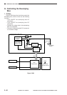
The current value at this time is checked by
the current detection circuit, and the result is
sent to the microprocessor.
In response, the microprocessor forwards
the result to the microprocessor (Q301) on
the DC controller, which determines the pri-
mary charging roller bias application voltage
based on the result.
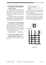
Caution:
You must enter the APVC value indicated on
the label attached to the composite power
supply PCB whenever you have replaced the
composite power supply PCB in service mode
No. 315 and No. 316. (See the Service
Handbook.)
Caution:
You must enter the APVC correction voltage
value as indicated on the label attached to the
front of the drum unit whenever you have
replaced the drum unit. (See the Service
Handbook.)
>
>