


3–45
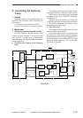
OPERATIONS AND TIMING
COPYRIGHT
©
1998 CANON INC. CANON NP6621 REV.0 FEB. 1998 PRINTED IN JAPAN (IMPRIME AU JAPON)
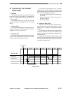
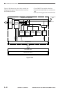
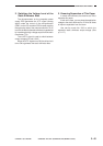
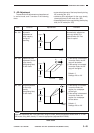
2. Switching the Voltage Level of the
Static Eliminator Bias
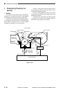
The microprocessor on the composite power
supply PCB generates the JCTL signal (analog
signal) under the control of the microprocessor
(Q301) on the DC controller PCB, thereby causing
the secondary side of the main transformer (T4) to
turn ON; the bias for the static eliminator is generated
by increasing the high-voltage output from the main
transformer (T4).
The JLVCTL signal is used to switch between
output voltages 2.5 and 4.0 KV.
When the JCTL signal turns ON, the drive circuit
turns ON to generate the static eliminator bias.
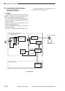
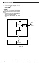
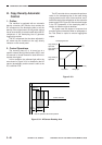
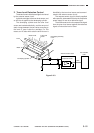
3. Ensuring Separation of Thin Paper
In certain environments, the machine can fail to
separate thin paper.
If such is the case, you may keep the application
voltage to the static eliminator to 4.0 kV at all times
to improve separation from the drum.
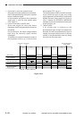
Use service mode No. 506 to switch the
separation static eliminator output voltage. (See
p. 3-117.)