


3–101
OPERATIONS AND TIMING
COPYRIGHT
©
1998 CANON INC. CANON NP6621 REV.0 FEB. 1998 PRINTED IN JAPAN (IMPRIME AU JAPON)
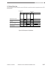
V. POWER SUPPLY
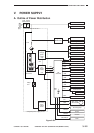
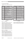
A. Outline of Power Distribution
Figure 3-501
Door
switch
Power
switch
Power
plug
FU2
T1
Main
transformer
High-
voltage
power
supply
unit
DC
controller
Scanning
lamp
control
circuit
composite power supply circuit
DC
Power
supply
unit
BAT
301
Cassette heater
Fixing heater
Charging roller
Developing cylinder
Transfer roller
Solenoids/Clutches
Fans
Motors
Pre-exposure lamp
CC-IVN
Counter
Scanning lamp
Deck
M1
+5V
+24V
+5V
+24V
+5V
+5V
+5V
+24V
+5V
+24V,5V
+24V,5V
+34V,24V,5V
+5V
+30V
+24
Relay
RL1
+30V
Static eliminator
Anti-condensation
heater
Drum heater
Antenna sensor
Intensity sensor
AE sensor
Sensors
+24V
+24V
+24V
+24V
+24V
Control panel
Main motor
driver PCB
Sorter
DF/RDF
Fixing heater
driver PCB
DS1