


3–79
OPERATIONS AND TIMING
COPYRIGHT
©
1998 CANON INC. CANON NP6621 REV.0 FEB. 1998 PRINTED IN JAPAN (IMPRIME AU JAPON)
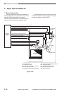
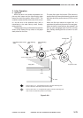
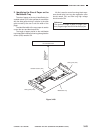
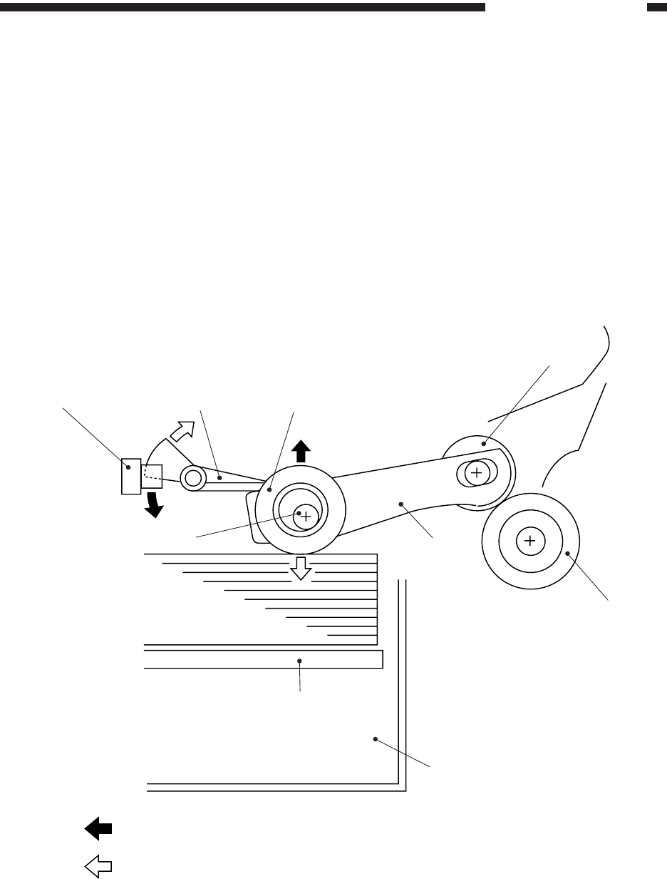
3. Lifter Operation
a. Operation
When the deck is slid inside the pedestal, the
pick-up roller lowers and the light-blocking plate
leaves the deck lifter position sensor (PS3). The
condition causes the lifter drive clutch (CL4) to turn
on, and the drive of the pedestal motor (M1) is
transmitted to the cable take-up shaft, thereby
raising the lifter.
The lifter keeps rising until the deck lifter position
sensor (PS3) detects the top sheet of the paper
stack placed on the lifter.
The deck lifter upper limit sensor (PS4) serves to
stop the lifter in the event that the sensor arm should
block the deck lifter position sensor (PS3) for some
reason.
When the lifter has reached its upper limit, it is
maintained in position by the work of one-way gear.
When the deck is removed from the pedestal, the
take-up gear disengages itself from the one-way
gear, thereby allowing the lifter to lower in its own
weight.
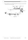
Lifter
: Pick-up roller up, i.e., the light-blocking plate of the lifter detecting lever
lowers to block the deck lifter position sensor (PS3)
Deck
Separation roller
Pick-up
roller arm
Pick-up roller shaft
Copy paper
Deck lifter position sensor
(PS3)
Lifter detecting
lever
Paper detecting
spacer
Feeding roller
: Pick-up roller down, i.e., the light-blocking plate of the lifter detecting lever
rises to leave the deck lifter position sensor (PS3)
Figure 3-434