


4–5
COPYRIGHT
©
1998 CANON INC. CANON NP6621 REV.0 FEB. 1998 PRINTED IN JAPAN (IMPRIME AU JAPON)
MECHANICAL SYSTEM
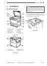
II. DRIVE SYSTEM
A. Scanner Drive System
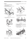
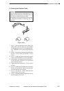
1. Removing the Scanner Drive Motor
1) Remove the copy board glass.
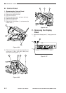
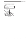
2) Remove the spring q, the E ring w, the tensioner
e, and the belt r.
Figure 4-201
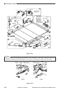
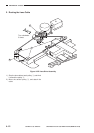
3) Remove the upper rear cover.
4) Disconnect the connector t of the motor, and
remove the two screws y.
5) Remove the spring u and the scanner drive
motor i.
Figure 4-202
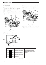
Caution:
When mounting the scanner driver motor, be
sure to make the appropriate adjustments as
follows:
1) Hook the spring u on the metal plate, and fix
the scanner driver motor in place with screws
y; then, give the screws y counterclock-
wise half turn to free it.
2) Push the motor down, and then shift it to the
left and right.
3) Where the motor stops, tighten the screws
y (on the right and then left).
4) Fit the tensioner e, and mount the spring q
and the E-ring w.
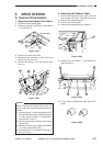
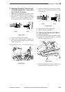
2. Removing the Scanner Cable
1) Remove the copyboard cover, right cover, left
cover, upper rear cover, and lower rear cover.
2) Remove the copyboard glass.
3) Remove the control panel.
4) Remove the copyboard cover support q.
Figure 4-203
5) Remove the ten screws w, and remove the
upper left stay e.
Figure 4-204
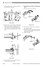
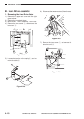
6) Fix the cable in place using cable clips (FY9-
3010).
Figure 4-205
1
2
3
2
2
2
6
8
6
7
5
1
4
3
2
Scanner wire