


3–57
OPERATIONS AND TIMING
COPYRIGHT
©
1998 CANON INC. CANON NP6621 REV.0 FEB. 1998 PRINTED IN JAPAN (IMPRIME AU JAPON)
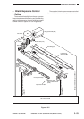
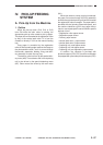
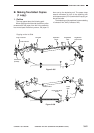
IV. PICK-UP/FEEDING
SYSTEM
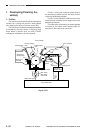
A. Pick-Up from the Machine
1. Outline
When the pick-up clutch (CL2, CL3, or CL5)
turns ON while the main motor is rotating, the
appropriate pick-up roller rotates to pick up paper.
The paper is then forwarded to the registration roller
by way of the vertical path roller if it is from the
cassette or directly if it is from the manual feeding
tray.
Copy paper is controlled by the registration
roller so that its leading edge matches the image on
the photosensitive drum, and it is moved through
the transfer, separation, feeding, fixing, and deliv-
ery assembly to reach the copy tray.
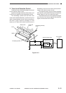
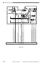
The delivery roller is driven by the special deliv-
ery motor (M6). The set-back roller in the duplexing
unit is also driven by the special duplexing motor
(M7). Other motors are driven by the main motor
(M1).
When two-sided or overlay copying is selected,
the paper first moves through the fixing assembly
and then through the duplexing unit before it reaches
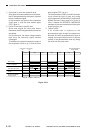
the registration roller once again. The paper path is
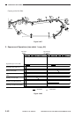
provided with the following photointerrupters, and
the machine identifies a jam if copy paper fails to
reach or move past specific sensors within specific
periods of time:
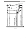
• Registration roller paper sensor
• Separation paper sensor
• Delivery paper sensor
• Vertical path roller 1 paper sensor
• Vertical path roller 2 paper sensor
• Duplexing unit outlet paper sensor
• Duplexing unit inlet paper sensor
• Duplexing unit pre-registration paper sensor
In addition, the cassette is provided with
photointerrupters (PS4, PS13) and the multifeeder
is equipped with yet another photointerrupter (PS5).