


4–29
COPYRIGHT
©
1998 CANON INC. CANON NP6621 REV.0 FEB. 1998 PRINTED IN JAPAN (IMPRIME AU JAPON)
MECHANICAL SYSTEM
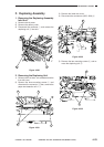
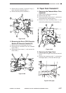
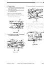
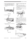
8) Remove the E-ring !1; then, remove the gear
!2, parallel pin, and pulley cover (front/rear in
common).
Figure 4-357
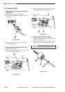
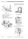
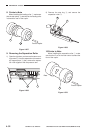
9) Remove the end of the wire from the pulley
(front/rear in common).
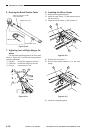
10) Remove the fastener !3 from the wire relay
assembly; then, remove the pulley cover, and
remove the wire from the pulley (front/rear in
common).
Figure 4-358
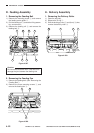
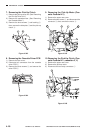
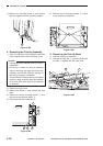
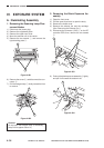
6) Remove the mounting screw y from the front,
and remove the oil damper plate u.
Figure 4-355
7) Remove the E-ring i from the lifter drive shaft
(rear); then, remove the gear o, two washers,
and spring !0.
Figure 4-356
7
6
9
10
8
11
12
13