


COPYRIGHT
©
1998 CANON INC. CANON NP6621 REV.0 FEB. 1998 PRINTED IN JAPAN (IMPRIME AU JAPON)
CHAPTER 3
OPERATIONS AND TIMING
In outline diagrams, represents mechanical drive paths, and indicates electrical
signal paths.
Signals in digital circuits are identified as ‘1’ for High and ‘0’ for Low. The voltage of signals,
however, depends on the circuit.
Nearly all operations of the product are controlled by a microprocessor; the internal workings
of the processor are not relevant to the service person’s work and, therefore, are left out of the
discussions. By the same token, no repairs are prescribed for the PCBs at the user’s premises; for
this reason, PCBs are discussed by means of block diagrams rather than circuit diagrams.
For the purpose of explanation, discussions are divided into the following: from sensors to main
PCB input ports; from main output ports to loads; and minor control circuits and functions.
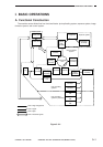
I. BASIC OPERATIONS ............................... 3-1
A. Functional Construction....................... 3-1
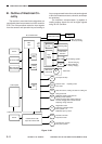
B. Outline of Electrical Circuitry ............... 3-2
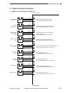
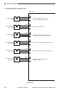
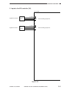
C. Inputs to the DC Controller .................. 3-3
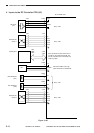
D. Outputs from the DC Controller ........... 3-8
E. Inputs to and Outputs from the Cassette
Feeding Module-B2 Driver PCB ........ 3-13
F. Inputs to and Outputs from the Cassette
Feeding Module-A2 Driver PCB ........ 3-14
G. Inputs to and Outputs from the Cassette
Feeding Unit-K1 Driver PCB ............. 3-16
H. Main Motor Control Circuit................. 3-21
I. Basic Sequence of Operations
(2 copies, continuous, AE) ................ 3-22
J. Original Size Detecton Control .......... 3-23
II. EXPOSURE SYSTEM ............................. 3-27
A. Varying the Reproduction Ratio ........ 3-27
B. Lens Drive System ............................ 3-27
C. Scanner Drive System....................... 3-31
D. Operations of the Scanner in Page
Separation Mode ............................... 3-34
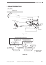
III. IMAGE FORMATION SYSTEM .............. 3-35
A. Outline ............................................... 3-35
B. Sequence of Operations
(image formation system) .................. 3-36
C. Controlling the Scanning Lamp ......... 3-37
D. Controlling the Primary Charging
Roller ................................................. 3-38
E. Controlling the Transfer Roller Bias .... 3-41
F. Controlling the Static Eliminator
Bias .................................................... 3-44
G. Controlling the Developing Bias ........ 3-46
H. Copy Density Automatic Control ....... 3-48
I. Developing/Cleaning Assembly ........ 3-50
J. Blank Exposure Control..................... 3-53
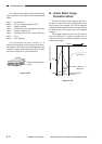
K. Primary Charging Roller Cleaning
Control ............................................... 3-55
L. Transfer Roller Locking/Releasing
Control ............................................... 3-56
IV. PICK-UP/FEEDING SYSTEM ................. 3-57
A. Pick-Up from the Machine ................. 3-57
B. Making Two-Sided Copies (1copy) ... 3-61
C. Duplexing Unit ................................... 3-63
D. Pick-Up from the Cassette Feeding
Module-A2 ......................................... 3-72
E. Pick-Up from the Cassette Feeding
Unit-K1 ...............................................3-74
F. Paper Deck Pedestal-K1 ................... 3-76
G. Multifeeder ......................................... 3-82
H. Identifying the Size of the Cassette... 3-85