


3–43
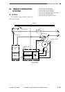
OPERATIONS AND TIMING
COPYRIGHT
©
1998 CANON INC. CANON NP6621 REV.0 FEB. 1998 PRINTED IN JAPAN (IMPRIME AU JAPON)
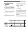
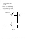
2. Turning ON/OFF the Transfer Roller
Bias
The TFWON signal is generated under the
control of the microprocessor on the composite
power supply PCB, thereby turning ON the
secondary side of the transfer transformer (T5) and
applying a DC bias to the transfer roller.
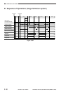
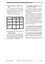
Table 3-301 shows combinations of signals
used to determine the transfer roller bias.
Transfer bias
output
Cleaning
bias output
Reference
bias output
(ATVC)
TREVON*
OFF
ON
OFF
TFWON*
ON
OFF
ON
TFWPWM
ON
OFF
OFF
Table 3-301
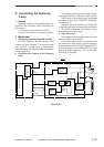
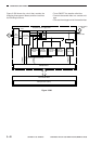
3. Controlling the Transfer Bias
Constant Voltage
The microprocessor on the composite power
supply PCB reads the TFWS (analog signal) from
the constant voltage control circuit while the transfer
DC bias is being generated and changes the duty
ratio so that the application voltage remains constant,
thereby controlling the TFWPWM signal.
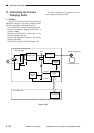
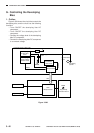
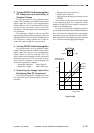
4. Correcting the Transfer Bias Voltage
Level (ATVC control)
To compensate for changes in the transfer
efficiency caused by changes in the environment or
deterioration of the transfer roller, the machine
automatically corrects the application voltage level
of the transfer bias.
During initial rotation after the Copy Start key is
pressed, a constant current (-10 µA) is sent to the
transfer roller. The microprocessor on the composite
power supply PCB reads the transfer roller
application voltage from the constant control circuit,
and the result is sent to the microprocessor (Q301)
on the DC controller, which in turn determines the
voltage to be applied to the transfer roller.
This control mechanism is executed once during
initial rotation after the Copy Start key is pressed;
therefore, the application voltage can never change
during continuous copying.
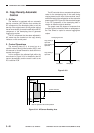
5. Current Limiter Circuit (transfer bias)
If changes in the environment or the like causes
an overcurrent to flow to the secondary side of the
transformer (T5) while the transfer bias is being
generated, the current limiter circuit starts control to
make sure that no current greater than 50 µA flows.
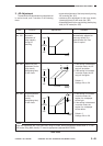
6. Current Limiter Circuit (cleaning bias)
If changes in the environment or the like causes
an overcurrent to flow to the secondary side of the
transformer (T5) while the cleaning bias is being
generated, the current limiter circuit starts control to
make sure that no current greater than 10 µA flows.