


5–28
INSTALLATION
COPYRIGHT
©
1998 CANON INC. CANON NP6621 REV.0 FEB. 1998 PRINTED IN JAPAN (IMPRIME AU JAPON)
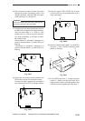
B. Installation to the Copier
Caution:
This model may not be available for sale in
some areas.
Caution:
Keep the following in mind when installing the
RDD to the copier:
1. This Accessory is to be installed by a qualified
personal.
2. Make sure the copier has been properly in-
stalled before starting the work.
3. Keep the copier’s power cord disconnected
during the work.
4. Be sure to use the appropriate screws (length,
diameter).
5. Make sure the computer in the service station
has been properly loaded with the RDD’s set-
tings data.
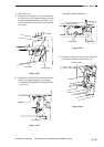
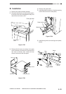
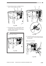
1) Remove the two screws w to detach the RDD’s
top cover q.
Fig. 5-802
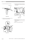
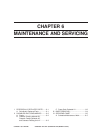
2) Connect the Power Supply Unit’s connector e
to the RDD’s connector r as shown.
Fig. 5-803
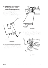
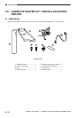
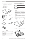
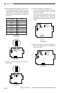
VIII.INSTALLING THE RE-
MOTE DIAGNOSTIC
DEVICE II
A. Unpacking
Fig. 5-801
q RDD ....................................................... 1 unit
w Power Supply Unit ................................. 1 unit
e Screw (M4×6) ........................................ 4 pcs.
r Harness band ........................................ 2 pcs.
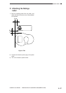
t Switch setting label ................................ 1 pcs.
y Grounding wire* ..................................... 1 pc.
u Ferrite core ............................................ 1 pc.
*Not used.
u
q
t
w
e
r
y
r
e
w
q
w