


3–127
OPERATIONS AND TIMING
COPYRIGHT
©
1998 CANON INC. CANON NP6621 REV.0 FEB. 1998 PRINTED IN JAPAN (IMPRIME AU JAPON)
VIII. STANDARDS AND
ADJUSTMENTS
A. Electrical
1 Adjustment after Replacing
PCBs
You must perform the following adjustments
whenever you have replaced the following PCBs:
a. DC Controller PCB
1) Start service mode (adjustment mode [3]), and
enter the settings indicated on the Service
Mode label attached behind the front door.
2) Perform the multifeeder paper width sensor
adjustment.
3) Perform scanning lamp intensity adjustment.
4) Perform AE adjustment.
As necessary, change the settings of service
mode and user mode.
Caution:
If you changed any of the settings indicated in
the Service Mode label, be sure to record the
new settings on the label.
b. Composite Power Supply PCB
1) Select service mode No. 315 through No. 318
(adjustment mode [3]), and enter the settings
indicated on the label attached to the composite
power supply PCB.
Be sure to record any new settings in the Ser-
vice Mode label.
c. AE Sensor PCB
1) Perform AE adjustment.
Caution:
If you changed any of the settings indicated in
the Service Mode label, be sure to record the
new settings on the label.
d. Light Adjustment Sensor PCB
1) Perform scanning lamp intensity adjustment.
2) Perform AE adjustment.
Caution:
If you changed any of the settings indicated in
the Service Mode label, be sure to record the
new settings on the label.
2 Adjusting the Scanning Lamp
Intensity
Select service mode No. 407.
1) Place the Test Sheet NA3 on the copyboard,
and close the copyboard cover.
2) Turn OFF AE, and make copies in continuous
mode at copy density 5 and VR850 (DC bias) at
center.
3) Press the zoom + keys or zoom - key so that the
optimum image is obtained.
• If the image is too light, press the zoom + key.
• If the image is too dark, press the zoom - key.
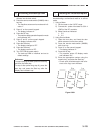
Reference:
1. What is referred to as optimum image is an
image in which gray scale No. 8 on the copy
corresponds to gray scale No. 4 through
No. 7 on the Test sheet while the copy is
free of fogging.
2. Turning the VR excessively can cause E220
to be displayed. If this is the case, turn the
VR 301 to the center position, turn OFF/ON
the power, and make adjustments once
again.
Caution:
After making the adjustment, be sure to perform
AE adjustment.
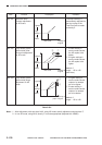
3 AE Adjustment
Perform AE adjustment using the following three
service modes:
q AE Basic Adjustment
No. 410 scanner forward stop
No. 408 scanning lamp ON check
No. 208 AE sensor voltage display
No. 301 AE scan lamp intensity automatic ad-
justment
w No. 302 AE mode copy density (developing
bias) reference adjustment
e No. 303 AE mode copy density (developing
bias) slope adjustment
If the copy density is not optimum after perform-
ing AE basic adjustment q No. 410, No. 408, No.
208, and No. 301, try w No. 302 and e No. 303 in
sequence.