3–54
OPERATIONS AND TIMING
COPYRIGHT
©
1998 CANON INC. CANON NP6621 REV.0 FEB. 1998 PRINTED IN JAPAN (IMPRIME AU JAPON)
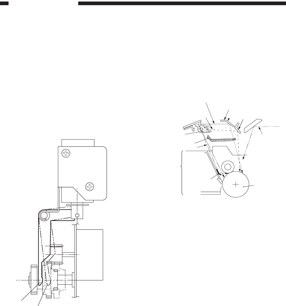
2. Blanking the Non-Image Area (re-
duction)
In reduction mode, the change solenoid (SL1)
turns ON, and the lens is moved to suit the selected
reduction ratio. At this time, turning the change
solenoid (SL1) OFF allows the drive of the lens
motor to be transmitted to gear A/B; the slide shutter
(rear/front) moves for the distance corresponding to
the selected reduction ratio. In this condition, the
exposure window opens, and the light from the pre-
exposure lamp is directed to the photosensitive
drum through the size blanking reflecting plate.
3. Blanking the Leading/Trailing Edge
Margin and Sheet Gap
The microprocessor (Q301) on the DC controller
turns ON/OFF the blanking shutter solenoid drive
signal (BSSLD*), thereby opening/closing the open/
close shutter to blank out the leading/trailing edge
margin or the gap between sheets of paper.
A
B
Figure 3-316
Size blanking optical path
Full blanking
optical path
Open/close
shutter
Slide shutter
Pre-exposure optical path
Drum
cartridge
Drum cleaning
assembly
Pre-exposure
reflecting plate
Size blanking
reflecting plate
Full blanking reflecting plate
Image exposure
optical path
Photosensitive
drum
Figure 3-317


