


3–21
OPERATIONS AND TIMING
COPYRIGHT
©
1998 CANON INC. CANON NP6621 REV.0 FEB. 1998 PRINTED IN JAPAN (IMPRIME AU JAPON)
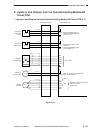
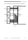
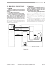
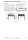
H. Main Motor Control Circuit
1. Outline
Figure 3-121 shows the circuit that controls the
main motor (M1), and the circuit has the following
functions:
q Turns ON/OFF the main motor.
w Controls the main motor to a specific speed.
The main motor (M1) is a DC motor equipped
with a built-in clock pulse generator. When the
motor rotates, clock pulse signals (MMCLK*) are
generated according to the revolution of the motor.
The speed control circuit controls the main motor
(M1) to a specific speed by matching the phase of
the frequency of the reference signal with the
frequency of the clock pulses.
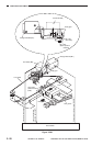
2. Operations
When the main motor signal (MMD) from the DC
controller circuit goes ‘1’, the motor driver drive
circuit turns ON, thereby causing the main motor
(M1) to rotate at a specific speed.
While the main motor is rotating at a specific
speed, the motor driver PCB sends the constant
speed status signal (MLOCK*0) to the DC controller
PCB. If a fluctuation occurs in the rotation of the
main motor for some reason, the MLOCK* signal
goes ‘1’.
If MLOCK*=0 continues for about 1 sec while
the main motor drive signal (MMD) is ‘1’, the DC
controller identifies an error condition and stops the
main motor and issues ‘E010’ at the same time.
Figure 3-121
J 501
- 1
- 2
J 502
- 2
J 312A
- 8
J 502
- 1
J 312A
- 7
36V
J 206
MMD
MLOCK*
MMCLK
M1
DC controller
PCB
Power
Supply
PCB
Phase control
circuit
Reference signal
Drive circuit
Clock pulse generator
Drive
current
Main motor
Hall IC output
Main motor driver PCB