


3–38
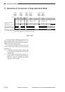
OPERATIONS AND TIMING
COPYRIGHT
©
1998 CANON INC. CANON NP6621 REV.0 FEB. 1998 PRINTED IN JAPAN (IMPRIME AU JAPON)
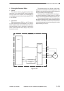
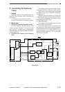
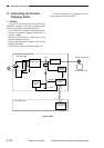
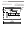
D. Controlling the Primary
Charging Roller
1. Outline
Figure 3-304 shows the circuit that controls the
application voltage of the primary charging roller,
and the circuit has the following functions:
• Turns ON/OFF the primary charging roller bias.
• Controls the primary charging roller bias to a
constant voltage.
• Switches the application voltage level of the
primary charging roller bias.
• Controls the application voltage of the primary
charging roller bias.
• Corrects the scanning lamp ON voltage level.
The main transformer (T1) generates the pri-
mary voltage controlled by U402.
Figure 3-304
T1
PDCS
Composite power supply PCB
Main transformer
Rectifier circuit
Current
detection
circuit
Filter circuit
T4
24V
Voltage
detection
circuit
Microprocessor
U402
Q301 (master)
Microprocessor
PCTRLS
PCURS
Primary charging roller
Photosensitive drum
DC controller PCB