


3–37
OPERATIONS AND TIMING
COPYRIGHT
©
1998 CANON INC. CANON NP6621 REV.0 FEB. 1998 PRINTED IN JAPAN (IMPRIME AU JAPON)
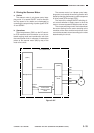
The machine exerts phase control by the zero-
cross signal (ZXDP) to stabilize the light intensity.
The intensity of the scanning lamp is switched
controlled by the LIGHT INTENSITY CONTROL
command (FLS).
During AE exposure, however, the voltage (70
V) applied to the scanning lamp remains the same.
The NP6621 adjusts the copy density using its
development bias; see p. 3-26.
c. Error Protection
The condition of the scanning lamp is monitored
using the LIGHT signal (LGHT).
If the LIGHT signal (LGHT) is received by the
DC controler for about 20 sec, the error detection
circuit generates the AC SHUTOFF signal (ACOFF)
to force the relay (K1) on the AC driver OFF, thereby
cutting AC power supply (p. 3-101). In this case,
E220 error is displayed.
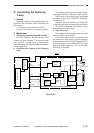
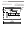
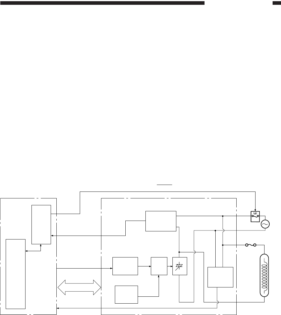
C. Controlling the Scanning
Lamp
1. Outline
The scanning lamp (LA1) is controlled by the DC
controller PCB; see Figure 3-303. Specifically, the
DC controller:
• Turns the scanning lamp ON and OFF.
• Controls the intensity of the scanning lamp.
2. Mechanism
a. Turning the Scanning Lamp ON and OFF
The CPU (Q308) on the DC controller PCB
controls the lamp regulator. The scanning lamp
goes ON/OFF through serial communication
interface between DC controller PCB and Composite
power supply PCB.
b. Controlling the Intensity of the Scanning
Lamp
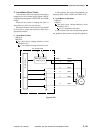
Figure 3-303
Lamp ON
detection
circuit
ACOFF
J307
-2
J307
-4 LGHT
J5
-11
-6 FLS
-13 ZXDP -2
-9
W15
W4
-3
J3
-1
CPU (Q308)
Error detection
circuit
Intensity
switching
circuit
Phase
control
Triac-
triggering
circuit
Switching
circuit
Composite power supplyDC controller PCB
Relay
(K1)
Power Supply
Scanning
lamp
(LA1)
Zero-cross
detection
circuit