


3–27
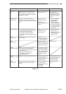
OPERATIONS AND TIMING
COPYRIGHT
©
1998 CANON INC. CANON NP6621 REV.0 FEB. 1998 PRINTED IN JAPAN (IMPRIME AU JAPON)
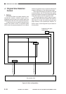
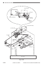
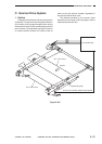
B. Lens Drive System
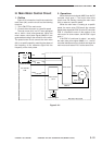
1. Outline
The lens drive system is driven by the lens motor
(M3), and the drive generated by the lens motor is
transmitted to the blanking shutter exposure unit
through a relay gear. (See p. 3-53.)
To move the lens, the relay gear is engaged with
the lens gear by turning ON the change solenoid
(SL1). When the lens motor rotates in the direction
of the arrow in this condition, the lens moves in the
direction of enlargement (
) because of the drive
coming through the relay lens gear and the lens
cable.
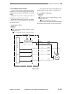
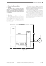
In reduction mode, the blank exposure shutter
operates according to the degree of movement of
the lens, thereby blanking out both sides of the copy
to suit the selected reduction ratio.
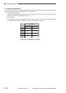
The machine’s scanner lens home position
sensor (PS2) is located in the middle of the scanner
lens drive rail so that the scanner lens home position
may be detected quickly at power-on, thereby
shortening the first copy time. (Additionally, a mere
press on each Ratio button causes the scanner lens
to move to the appropriate position to shorten the
first copy time.)
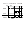
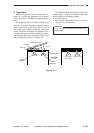
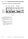
II. EXPOSURE SYSTEM
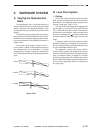
A. Varying the Reproduction
Ratio
The reproduction ratio in the axial direction of
the photosensitive drum is varied by the lens drive
system, and that in the peripheral direction of the
photosensitive drum is varied by the scanner drive
system.
The lens drive system uses a zoom lens, and the
reproduction ratio in the axial direction of the photo-
sensitive drum is varied by changing both the posi-
tion of the lens and the focal distance as shown in
Figure 3-201.
The scanner drive system moves the No. 1
mirror faster in relation to the peripheral speed of
the photosensitive drum (reduction) or slower
(enlargement), thereby varying the reproduction
ratio in the peripheral direction of the photosensitive
drum.
F
F'
F1
F2
F2'
F1'
DIRECT
REDUCE
ENLARGE
Figure 3-201