


3–2
OPERATIONS AND TIMING
COPYRIGHT
©
1998 CANON INC. CANON NP6621 REV.0 FEB. 1998 PRINTED IN JAPAN (IMPRIME AU JAPON)
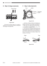
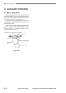
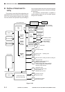
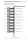
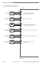
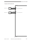
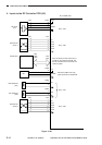
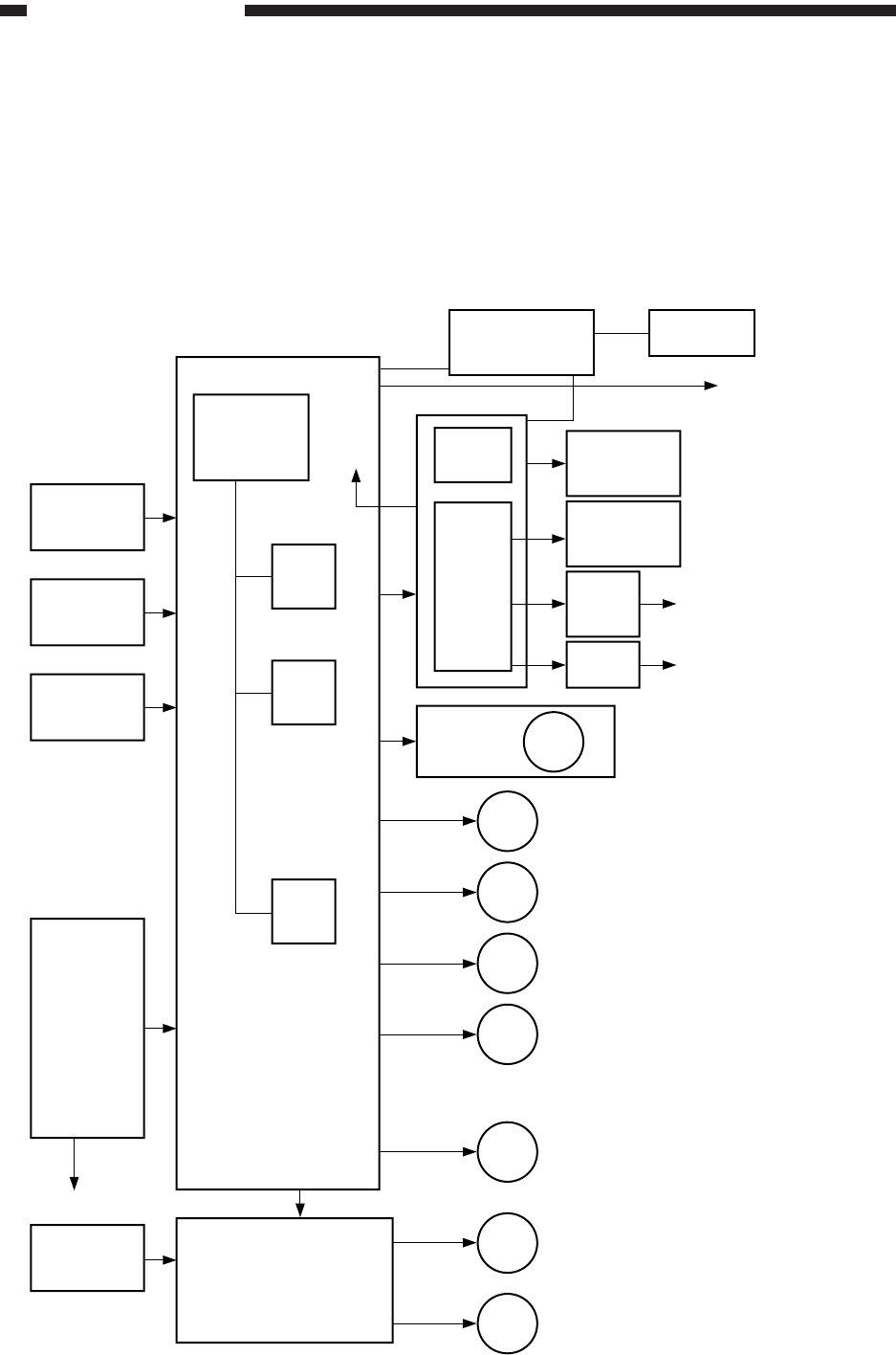
B. Outline of Electrical Cir-
cuitry
The machine’s most electrical mechanisms are
controlled by the microprocessor on its DC controller
PCB. The microprocessor reads the input signals
from the sensors and operation keys according to
its pre-programmed instructions and sends signals
to drive such loads as motors, solenoids, and lamps
as necessary.
The machine’s microprocessor is capable of
reading analog signals as well as digital signals
using its A/D converter.
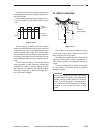
Figure 3-102
Sensor
AE sensor PCB
Main thermistor
Sub thermistor
Control panel
Control card (accessory)
Sensor
DC controller PCB
Cassette driver PCB/
Paper deck driver PCB
(accessory)
Composite power supply
High-
voltage
circuit
Main motor
driver PCB
RDF (accessory)
Sorter (accessory)
Scanning lamp
Toner level
detection
Bias PCB
Heater driver PCB
Developing cylinder
Transfer charging
Static eliminator
Primary charging
Main motor
Pre-exposure lamp
Motor
Scanner motor
Lens motor
Duplexing motor
Fan
Heat exhaust fan, Feeding fan,Scanner cooling fan
Change solenoid
Multifeeder holding plate solenoid
Blanking shutter solenoid
Primary charging roller cleaning solenoid
Transfer charging roller release solenoid
Duplexing change solenoid
Registration clutch
Duplexing registration clutch
Pick-up clutch 1, 2
Multifeeder pick-up clutch
Motor
Cassette unit motor
Paper deck motor
Cassette pick-up clutch
Deck pick-up clutch
CL
CL
SL
LA
M1
HV
Fixing roller
heater
CPU
Q301
CPU
Q307
ROM
Q308
RAM
Q311
IPC
+5V
+24V
+34V