4–16
COPYRIGHT
©
1998 CANON INC. CANON NP6621 REV.0 FEB. 1998 PRINTED IN JAPAN (IMPRIME AU JAPON)
MECHANICAL SYSTEM
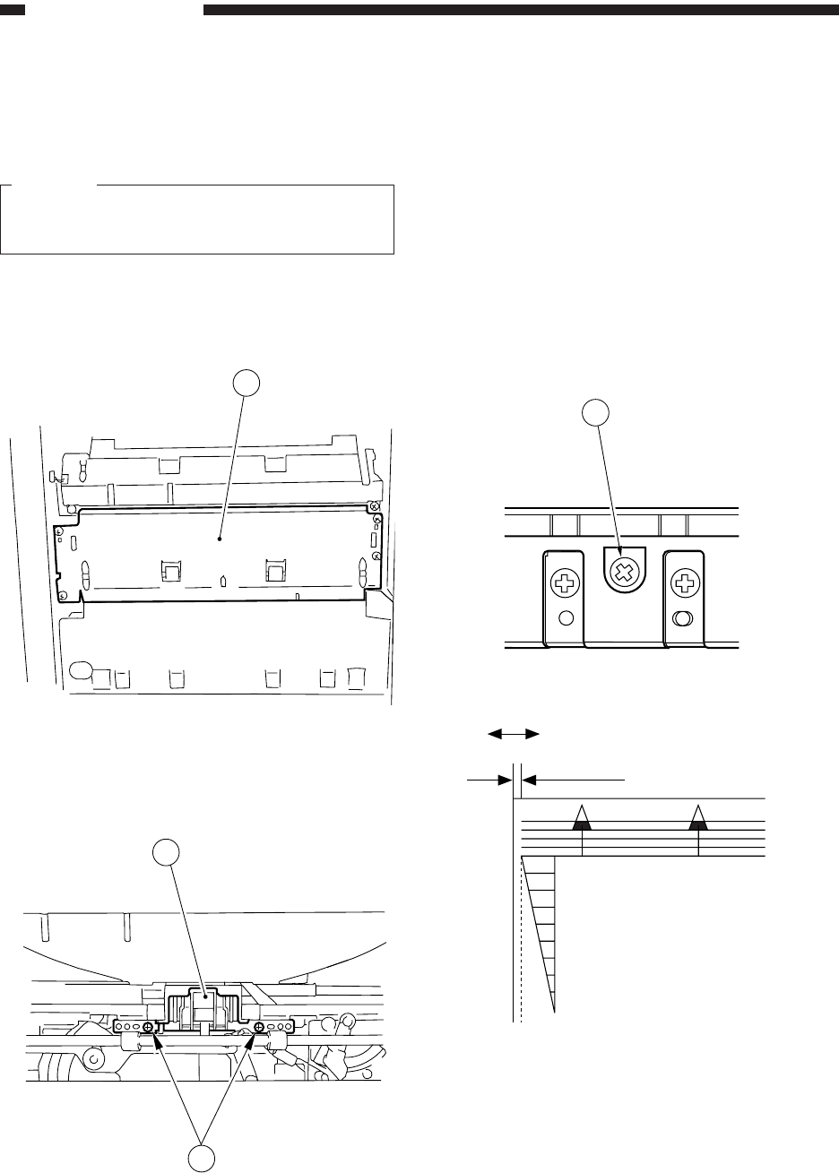
5. Adjusting the Left/Right Registration
Make adjustments so that the image position is
as indicated in Figure 4-308 when the Test Sheet is
copied in Direct.
a. Pick-Up from the Cassette
Turn the screw q shown in Figure 4-307 to
adjust the position of the cassette hook plate.
standards: 0 ± 1.5 mm
• CW direction: moves the paper in the direc-
tion of – in Figure 4-308
• CCW direction:moves the paper in the direc-
tion of + in Figure 4-308
Figure 4-307
Figure 4-308
1
2
3
1
(-) (+)
0±1.5mm
0
2
4
6
8
10
4. Removing the Separation Pad
1) Fully open the right door. (Remove the tension
tape from the door.)
Caution:
Take care not to open the right door exces-
sively.
2) Remove the front right cover.
3) Remove the vertical path guide q (upper; four
screws).
Figure 4-305
4) Remove the two screws w, and remove the
separation pad unit e.
Figure 4-306


