


3–6
OPERATIONS AND TIMING
COPYRIGHT
©
1998 CANON INC. CANON NP6621 REV.0 FEB. 1998 PRINTED IN JAPAN (IMPRIME AU JAPON)
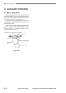
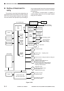
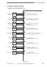
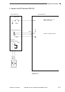
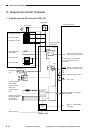
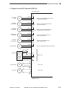
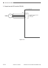
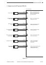
4. Inputs to the DC Controller PCB (4/5)
Figure 3-106
J 651
- 6
- 5
- 4
- 3
- 2
- 1
J 318
- 7
- 8
- 9
- 10
- 11
- 12
CS
CSZ1
CSZ2
CSZ3
CSZ4
Cassette size
sensor 2
See p. 3-85.
See p. 3-87.
J 651
- 6
- 5
- 4
- 3
- 2
- 1
J 318
- 1
- 2
- 3
- 4
- 5
- 6
J 316B
- 6
- 7
- 8
J 324A
- 1
-2
J 324A
- 5
-6
J 305
J 306
J 801
J 802
J 803
CS
CSZ1
CSZ2
CSZ3
CSZ4
Cassette size
sensor 1
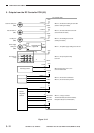
Control panel
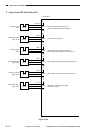
Main thermistor
(TH1)
Sub thermistor
(TH2)
See p. 3-85.
J 601
- 1
- 2
- 3
- 4
J 310A
- 9
- 8
- 7
- 6
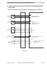
AE sensor
(1/2)
See p. 3-48.
AE
AEREF
+24V
5V
MFPWD
TH1
TH2
VR1
DC controller PCB
Keys and LEDs are wired in the form of
a matrix on the control panel PCB, and
the DC controller turns on the LEDs and
reads key inputs.
Detects the width of the copy
paper stacked in the multifeeder.