


3–12
OPERATIONS AND TIMING
COPYRIGHT
©
1998 CANON INC. CANON NP6621 REV.0 FEB. 1998 PRINTED IN JAPAN (IMPRIME AU JAPON)
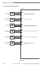
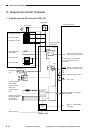
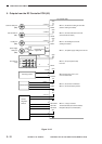
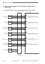
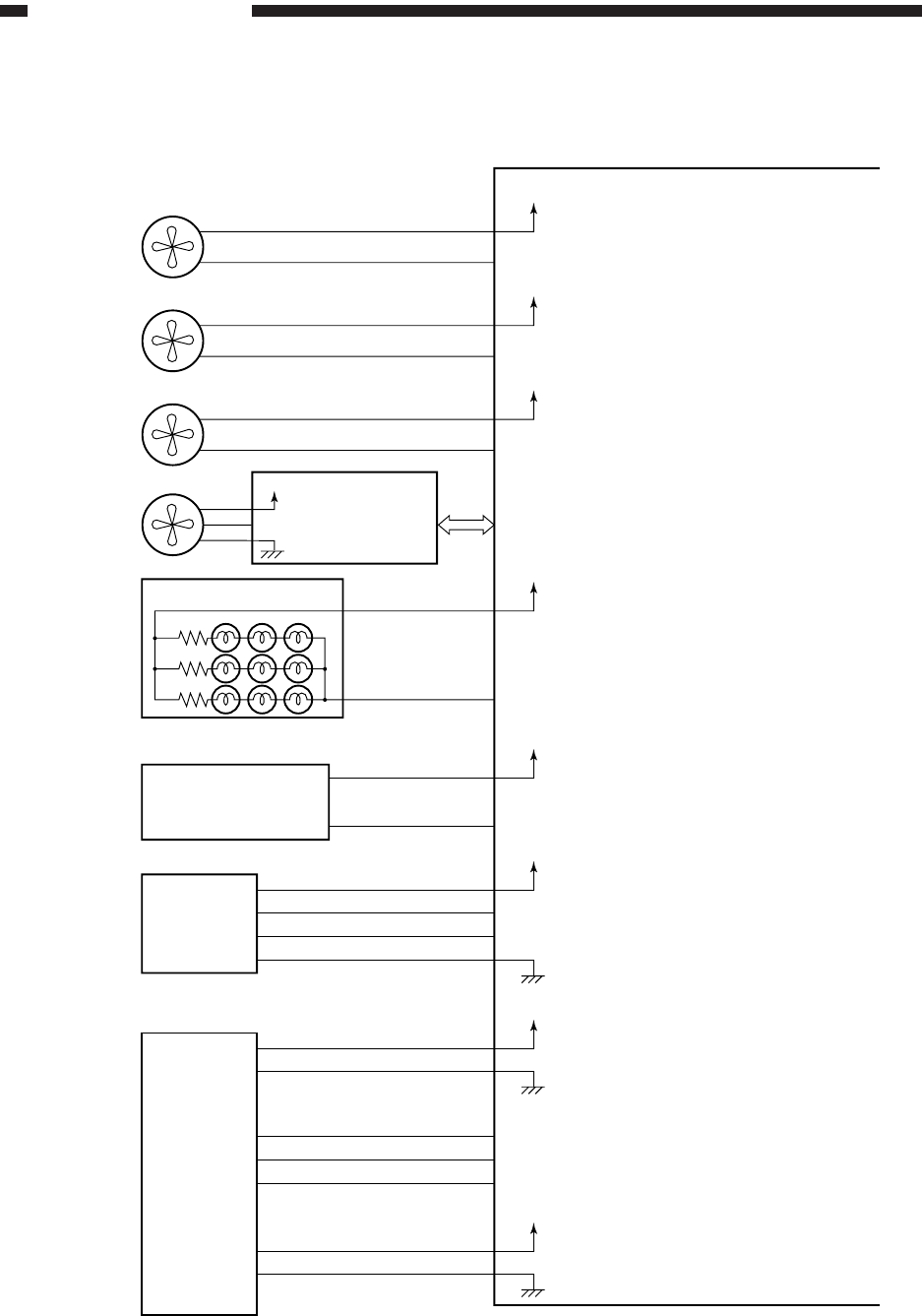
5. Outputs from the DC Controller PCB (5/5)
Figure 3-112
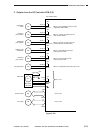
AST-CNTP*
+24V
J 315B- 2
- 1
J 314A- 7
- 8
J 315A
- 10
J307
- 9
J 315B
- 9
J 306A- 11
- 13
- 12
- 10
- 8
J 401
- 1
J12-4
-3
-2
- 2
HEFD*
+24V
FDFD*
+24V
PEXP*
+24V
TCNTD*
+5V
CCD*
CCDT*
- 6
- 5
- 4
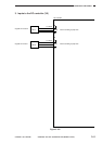
AST-TXD
AST-RXD
Heat exhaust fan
(FM1)
Pre-exposure
lamp
Feeding fan
(FM4)
Total copy counter
Control Card N
DC controller PCB
When '0', the heat exhaust fan turns ON.
(heat exhaust fan rotates)
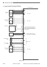
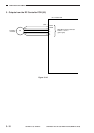
+24V
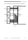
J 310A- 4
- 5
FM2D
Scanner cooling fan
(FM2)
When '0', the Scanner cooling fan turns ON.
(Scanner cooling fan rotates)
When '0', the pre-exposure lamp
turns ON.
When changes from '0' to '0', the
count is incremented.
When '0', the count is incremented.
When '0', the control card is present.
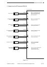
J 311A- 7
- 8
5V
- 2
- 3
24V
Remote
Diagnostic
Device II
When '0', a copy is counted.
Transmission data (IPC communication)
Reception data (IPC communication)
When '0', the feeding fan turns ON.
(feeding fan rotates)
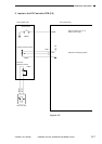
When '1', the power supply cooling fan turns ON.
Composite power
supply PCB
Power supply
cooling fan
(FM3)
+24V
PSCFD