


5–32
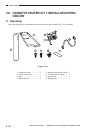
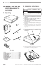
INSTALLATION
COPYRIGHT
©
1998 CANON INC. CANON NP6621 REV.0 FEB. 1998 PRINTED IN JAPAN (IMPRIME AU JAPON)
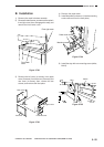
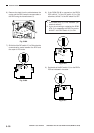
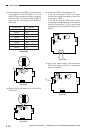
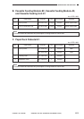
12) After making sure that LED5 !8 (red) has come
on, set the bits on the DIP switch 2 !6 on the
RDD’s PCB as indicated in the table, and press
the push switch 4 !7 to make sure that LED5 !8
(red) goes out, indicating that the RAM has
been reset.
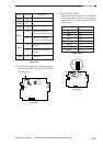
Table 5-803
Fig. 5-814
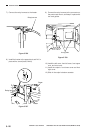
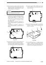
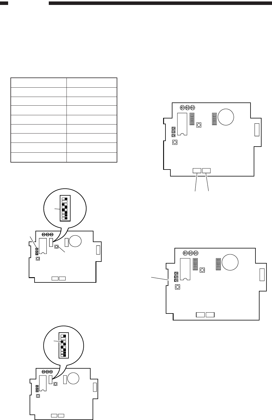
13) Shift bit 6 of the DIP switch 2 !9 on the RDD’s
PCB to OFF.
Fig. 5-815
bits on SW2
SW2-1
SW2-2
SW2-3
SW2-4
SW2-5
SW2-6
SW2-7
SW2-8
Setting
OFF
OFF
OFF
ON
OFF
ON
See step 9).
OFF
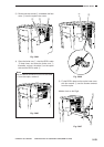
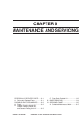
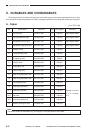
14) Connect the RDD to the telephone line.
If you are connecting the RDD on its own,
connect the modular jack cable to the RDD’s
connector @0 (LINE).
If you will be using the RDD’s extra circuit,
connect the existing telephone or fax machine
to the RDD’s connector @1 (TEL), and connect
the telephone circuit to the RDD’s connector @0
(LINE).
Fig. 5-816
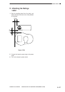
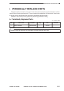
15) Call up the service station, and request the
RDD’s initial settings. (LED 4 @2 (red) starts to
flash upon receipt.)
Fig. 5-817
LED1LED2 LED3
2
1
LED5
LED6
LED4
IC6
SW1
SW4
SW3
6
1
BAT1
CN4
1
2
CN3 CN2
12345678
!9
SW2
LED1 LED2 LED3
2
1
LED5
LED6
LED4
IC6
SW1
SW4
SW3
6
1
BAT1
CN4
1
2
CN3 CN2
@1
@0
SW2
LED1 LED2 LED3
2
1
LED5
LED6
LED4
IC6
SW1
SW4
SW3
6
1
BAT1
CN4
1
2
CN3 CN2
@2
SW2
LED1LED2 LED3
2
1
LED5
LED6
LED4
IC6
SW1
SW4
SW3
6
1
BAT1
CN4
1
2
CN3 CN2
12345678
!6
SW2
!8
!7